Thank you for the clarification.... will try it outdecreasing the gain, may make this worse.
The feedback goes up as the gain goes down and that usually results in lower stability margins.
The little bit of overshoot in post127 confirms that compensation is not quite there yet.
You can go the other way as an experiment: increase the gain by paralleling the 820r with another. That reduces the feedback by 6dB.
If this clears the oscillation then it tells you the compensation needs further work to increase the stability margins. After that I can't help because this is the area where my lack of AC theory shows my limitations.
Overshoot is no sign of instability, and some topologies work best with a little overshoot. Ringing however is. Outright oscillation should not occur regardless of overshoot. Hopefully you are taking the square wave measurements without the RC filter.
I am doing measurements in the built amp so including input rc filter and output coil and zobel.
Try tuning the compensation without R24 first, since it can introduce some overshoot and harmless response quirks at RF.
Will do
Crackling when the volume is changed probably means the amp is going in and out of oscillation as the pot change resistance to ground and resistance to source (sometimes grounding the input causes oscillation, or it can be the other way, there is oscillation if the input is not grounded - either way, it should be addressed either as local parasitic oscillation or by adjusting the global compensation). If you cannot find the oscillation on the scope it's possible it's in the hundreds of MHz and is probably parasitic oscillation of the input FETs. Your input is heavily filtered by the input RC, but it's also possible that interactions through the input ground could cause oscillation. If this is the case you may have to try changing grounding arrangements. For instance grounding the heatsink to the PCB through a 47R resistor is something that may help. Or changing the order of connections along the ground trace.
Your scope plot shows oscillation in the crossover region where the output stage is slower than normal. To me this suggests that C17 may be too large.
Do you have a picture of the PCB so we can see the layout?
Crackling appeared after input went higher than 0.7vac and not only while turning the volume pot.
Touching the heatsink reduces this issue so I will ground it.
I am not using C17
Attachments
An ungrounded heatsink (or not directly decoupled to the PCB in some way) I've found often causes some sort of strange RF effect, so I always pay special attention to it.
Often touching the heatsink will reduce noise simply because when your body is grounded, it becomes a shield, and otherwise it tends to radiate whatever noise hits it back over it's entire surface area. So for instance as your finger approaches the circuit the noise will rise because your body is radiating noise, but when you touch the chassis the noise will suddenly drop, because your body is grounded and now acting as a shield. This can be distinguished from cases where touching something actually causes oscillation or stops it.
Often touching the heatsink will reduce noise simply because when your body is grounded, it becomes a shield, and otherwise it tends to radiate whatever noise hits it back over it's entire surface area. So for instance as your finger approaches the circuit the noise will rise because your body is radiating noise, but when you touch the chassis the noise will suddenly drop, because your body is grounded and now acting as a shield. This can be distinguished from cases where touching something actually causes oscillation or stops it.
He has no High Pass filter on the input of the amplifier.this calculator can help you....Online RC Highpass filter Calculator | XY Calculator
The NFB becomes the high pass filter and this is a poor way of re-designing the amplifier.
There could be a high pass filter in the source, or the source could have a DC blocking capacitor that is acting as a high pass filter, but it's not in the DCB1.
After increasing the gate to drain caps placed in all output mosfets the amp became stable and now I can play it loud (really loud) with all the input preamps I have available.
Sound lost all traces of sybilance and bass remains deep strong and detailed.
I will now build the second amp so I can listen in stereo and will play with compensation until I find voicing suitable to my system.
Off course the new board will have all mods suggested by the group.
Soon will report back with new subjective listening impressions.
PS: I am sure it was Miib that sugested these gate to drain small caps during the development of my first mosfet amp ( http://www.diyaudio.com/forums/solid-state/258549-assemblage-power-amp-23.html#post4101192 ).
They tend to reduce highs (the same way as miller caps do in the VAS) but to less extent.
They tend to reduce highs (the same way as miller caps do in the VAS) but to less extent.
before and after please?After increasing the gate to drain caps placed in all output mosfets the amp became stable
I think it was R.Cordell that suggested the gate to drain capacitor could be a Zobel of C+R and this extra zero has some benefit.
Can't remember the details.
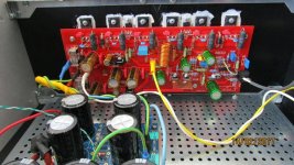
Just finished second board including mods as suggested and it worked right from the start.
Stability is no more an issue here.
Although it sounds fast with really good bass, the highs are slightly forward so I would like to reduce those.
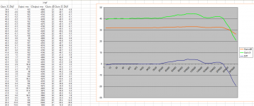
I made some measurements that indicate a rise in gain starting at 10k... not fenomenal but enough to be heard.
Gain is up for 1dB at 20k and 3dB at 60k.
Can I reduce high freq gain by using a cap over the FB resistor ? IMO it can increase FB at high freq so gain will be reduced but will it create instability issues ?
Stability is no more an issue here.
Although it sounds fast with really good bass, the highs are slightly forward so I would like to reduce those.
I made some measurements that indicate a rise in gain starting at 10k... not fenomenal but enough to be heard.
Gain is up for 1dB at 20k and 3dB at 60k.
Can I reduce high freq gain by using a cap over the FB resistor ? IMO it can increase FB at high freq so gain will be reduced but will it create instability issues ?
Attachments
An ungrounded heatsink (or not directly decoupled to the PCB in some way) I've found often causes some sort of strange RF effect, so I always pay special attention to it.
Often touching the heatsink will reduce noise simply because when your body is grounded, it becomes a shield, and otherwise it tends to radiate whatever noise hits it back over it's entire surface area. So for instance as your finger approaches the circuit the noise will rise because your body is radiating noise, but when you touch the chassis the noise will suddenly drop, because your body is grounded and now acting as a shield. This can be distinguished from cases where touching something actually causes oscillation or stops it.
Many years ago I worked for an outfit called ILP Electronics that made amplifier modules. One used power MOSFETs and worked fine. But when we had to change the types because of discontinued product we had a lot of trouble with rf oscillation and found that it was due to the tab of the device now being the source connection instead of the drain of the previous device. This was with the heatsink earthed/connected to 0V. As there were many customers for this module, it had to work with the heatsink floating or earthed. I seem to remember that beads were used on the leads. I hope this advice might be useful.
Can I reduce high freq gain by using a cap over the FB resistor ? IMO it can increase FB at high freq so gain will be reduced but will it create instability issues ?
Funny you'd mention that -- I just experimented with this in my Honey Badger today. The gain is flat with my Honey Badgers, but the sound changes quite a bit if the "LC cap" is added across the feedback resistor. Without the cap, the sound is very lively, but also a bit on the "bright" side. If the cap value is too high (5pF or more), the amp sounds boring. For even bigger values, the whole things starts ringing and oscillating, resulting in smoke and blown fuses. Oh, and the square waves didn't look the same in simulation and on the scope (so I just ignored the simulation). Conclusion: just give it a try, start with small cap values, and check the result on a scope.
before and after please?
I think it was R.Cordell that suggested the gate to drain capacitor could be a Zobel of C+R and this extra zero has some benefit.
Can't remember the details.
I use 220p G-S on N-channel lateral parts and 18p in series with 22R for P-channel laterals, though it's really pretty arbitrary. The rationale behind a much higher Cgs for the N-channel parts is to slow their rise times to better resemble those of the P-channel ones.
Stability is no more an issue here.
Cool!
Can I reduce high freq gain by using a cap over the FB resistor ? IMO it can increase FB at high freq so gain will be reduced but will it create instability issues ?
Yes, you can. It's a very standard stabilisation technique. Small values of capacitance will have a big effect in this spot, as they're effectively multiplied by the gain of the amp.
I have been playing with compensation and now I reached a sweet spot.
I am using TMC 120 2k2 500 and no cap over the feedback resistor.
Going from 1k8 to 2k2 in the TMC did remove sibilance while retaining good low freq attack and speed. (Not as good as with 1k8 but fair).. good compromise.
Now building timer and output protection for DC.
Will post final sch and pics latter.
Thank you all for your support.
Idling current on the mosfets is now 150mA.....
Also compared TMC with OMC and tone is very similar but with TMC bass is much snappier and seems to go lower.
Also compared TMC with OMC and tone is very similar but with TMC bass is much snappier and seems to go lower.
BTW, using Andrew's tech I measured and paired the source resistors to 0.3% (values between 0.1015 and 0.1012)
Been fiddling with feedback and found that with a little bit more I get more linearity and loose the spicy highs... so now I am using 22k for feedback resistor as in the sch in attach.
Now sounding BIG and highs almost acceptable... would like to make it sound BIG but sweet at the same time...
As more feedback helps, I believe the trick is to reduce distortion in the high freq so I would like to try more degeneration in the IPS.
Now I am using LSK170BL 5mA Idss running at 3.7mA (seems to me the sweetspot) and Rs are 22 ohm.
With these Rs I have -1.9mV offset.
I would like to rise these Rs to 100 ohm but simulation indicates a rise in offset.... (to 3mV)... is it normal ?
Would the 100ohm Rs reduce High freq distortion significantly ?
Please have a look at the latest sim....
Attachments
Emitter resistors (AKA degeneration) on the LTP will probably increase offset and distortion, but that doesn't mean they won't improve the sound. I think you will just have to try it. So far your experiments seem to indicate that harmonic distortion is not what is causing the problem.
Last edited:
- Status
- Not open for further replies.
- Home
- Amplifiers
- Solid State
- Very HQ power amplifier (Assemblage VII)