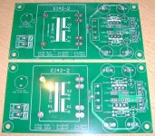
Ivan, I received the Dual-PSU PCBs today.
I have already built a PSU myself and do not see any ripple on the outputs.
In my opinion the 78xx/79xx regulators are much better than their reputation.
But maybe that my old Tektronix oscilloscope is no more sensitive 😀.
If you want to have a pair of PCBs: a pair incl. shipping cost 8€.
Best regards - Rudi
Attachments
Rudi I decided not to do this project and to see how dac and jg buffer behave first. Thank you anyway.
Sent from my HTC Sensation using Tapatalk
Sent from my HTC Sensation using Tapatalk
kit
Hi I have decided to take another route so I have a Rudi s kit and includes reichelt bom (49) ,ldr s,,motorised pot, lcd ,,
So if you are interested I will list with pic
regards john
Hi I have decided to take another route so I have a Rudi s kit and includes reichelt bom (49) ,ldr s,,motorised pot, lcd ,,
So if you are interested I will list with pic
regards john
Start populating my boards.If there are any tips and things to watch for please let me know.I've changed R24 from 2K2 to 330 Ohm is this correct?
hey there,
i bought this kit from jp in the swap meet section. i am finished populating it though i am still in search for the silonex optocouplers. does anybody here have a spare matching quad or could make an offer?
cheers
Fabian
i bought this kit from jp in the swap meet section. i am finished populating it though i am still in search for the silonex optocouplers. does anybody here have a spare matching quad or could make an offer?
cheers
Fabian
A future GB for the PCB, or has anyone a PCB left?
I have the Calvin Buffer PCB and parts (from the Paradise project) and I'll use the Paradise supply that is very capable. So I only need the PCB for the input selection.
Thanks
I have the Calvin Buffer PCB and parts (from the Paradise project) and I'll use the Paradise supply that is very capable. So I only need the PCB for the input selection.
Thanks
I am sorry, amsoque, I do not have any VCPre-PCBs left.
I am currently working on a new edition of the VCPre, having a buffer on-board and a separate PSU for the VCPre and the buffer.
But it will take some time, until I will be able to offer the new edition of my VCPre.
Best regards - Rudi
I am currently working on a new edition of the VCPre, having a buffer on-board and a separate PSU for the VCPre and the buffer.
But it will take some time, until I will be able to offer the new edition of my VCPre.
Best regards - Rudi
in this case, it's OK for me. I intended to finish this project to the and of the summer.
thank you for your efforts.
Which buffer will you put on the PCB?. Perhaps you'll give the possibility to use an external buffer. (like the Calvin that I already have)
Emil
thank you for your efforts.
Which buffer will you put on the PCB?. Perhaps you'll give the possibility to use an external buffer. (like the Calvin that I already have)
Emil
Hi Rudi.
You wrote in an email to use 33 Ohm for R24 istead of the printed Value of 2k2. But I cannot find any Picture of the Schematics with the parts enumerated! Could you give me a Picture of the PCB with all parts enumerated so I can locate R24?
Btw: Soldered the SMD Parts without problems. 🙂
Thank you in advance!
Greetings from around the corner! 😀
Ron
Last edited:
Rudi,
Just got around to soldering in IR sensor and everything programs fine and works with the exception of the volume control motor. When you press volume up or down I only see a few + and - millivolts accross the output but if I check them to ground they are about 3-4 volts. By the way if anyone needs a board I have a spare.
Bill
Bill: the signal to to power the motorized potentiometer is a PWM (a square wave output by the PIC processor) signal. You will not be able to measure it with a DMM.
Does the motorized potentiometer move at all?
Best regards - Rudi_Ratlos
Does the motorized potentiometer move at all?
Best regards - Rudi_Ratlos
If you've a board left I want thatRudi,
Just got around to soldering in IR sensor and everything programs fine and works with the exception of the volume control motor. When you press volume up or down I only see a few + and - millivolts accross the output but if I check them to ground they are about 3-4 volts. By the way if anyone needs a board I have a spare.
Bill
I am not seeing a pulse or square wave, you mentioned in the documentation the transistors may be reversed, they seem to be working in all the other positions. I tried one of the older chips in case the updated one may have been damaged but no change.
Bill
Bill
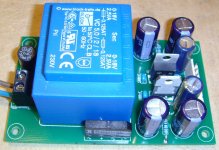
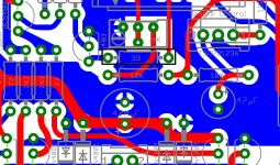
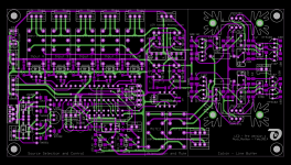
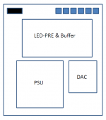
Gentlemen: as I told you in my post #608, I am currently working on an "integrated pre-amplifier, called LED-PRE", including an improved version of my VCPre, a line-buffer and a DAC
(well: I still need the permission of Jean-Paul and SUBBU to include it).
Find attached the current layout.
I have already built a prototype (2nd image), and the LED-Pre sounds very well, but I need to confirm my first impression.
I will keep you informed about this project.
Best regards - Rudi_Ratlos
P.S.: And, of course: I will use a very high sophisticated PSU for the LED-PRE.
Attachments

Last edited:
Great! The dac will be a separate board?"integrated pre-amplifier, called LED-PRE", including an improved version of my VCPre, a line-buffer and a DAC
- Status
- Not open for further replies.
- Home
- Group Buys
- Versatile and comfortable passive pre-amp