No problem, Jean-Paul!
One of my German DIY-friends has taken the job and will cut the auxiliary PCBs for all of us.
This is why I like to be a German DIYer! We are a team!
One of my friends (Gerhard) is a carpenter, the other one (Andreas) a precision engineer and Peter (who will cut the PCBs)
owns the needed tool to cut PCBs. And we help one another, when help is needed.
And I, myself: have some ideas and experience with the EAGLE - CAD software.
But be sure: I will not overstress their patience in Round 2 of this group-buy.
Best regards - Rudi_Ratlos
Last edited:
I did, Bill!
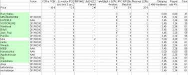
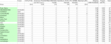
Sorry: I forgot to highlight your nickname on my spreadsheet.
Best regards - Rudi_Ratlos
Sorry: I forgot to highlight your nickname on my spreadsheet.
Best regards - Rudi_Ratlos
Jean-Paul: I have received your money transfer. Thank you.
The only change that is planned for the 2nd - round PCB is the replacement of the transformer.
I will use the TAMURA 3FD-316 in the 2nd round to support both 115 and 230 VAC primary.
I hope that it does not sound worse than the BLOCK transformer that I am using currently. But since you recommended it ... 🙄
Best regards - Rudi_Ratlos
Well I hope it does not sound different 😉 Even if it does I hope its stray field is smaller than the Block transformer. Would not be the first time German technology is beaten by Japanese technology...
Rudi,
Since I will be building for 115V maybe the second batch would be better for me as well. I would prefer to have the transformer mounted on the board, it keeps the layout tidy.
thanks
Bill
Since I will be building for 115V maybe the second batch would be better for me as well. I would prefer to have the transformer mounted on the board, it keeps the layout tidy.
thanks
Bill
I received your payment, Adrian. Thank you!
I have already begun and am collecting the ordered components for you!
I still have no idea how to solder the SMD-components: my eyes are growing older each day 😱 !
Can anybody give me an advice? Glueing it before soldering it?
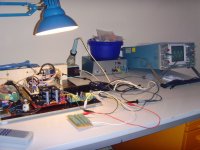
I am currently trying to "marry" the VCPre with my favourite ClassD-amplifier 😕 .
But the marriage does not look good, does it?
I remember that the input impedance of the connected amplifier should be at least (+/-) 24KOhm.
I will ask JLMAUDIO about the impedance of his L15D.
Best regards - Rudi_Ratlos
I have already begun and am collecting the ordered components for you!
I still have no idea how to solder the SMD-components: my eyes are growing older each day 😱 !
Can anybody give me an advice? Glueing it before soldering it?
I am currently trying to "marry" the VCPre with my favourite ClassD-amplifier 😕 .
But the marriage does not look good, does it?
I remember that the input impedance of the connected amplifier should be at least (+/-) 24KOhm.
I will ask JLMAUDIO about the impedance of his L15D.
Best regards - Rudi_Ratlos
Attachments
Looks and sounds great!!
SMD is quite easy once you get the hang of it.
You need flux!! A flux pen will do, but some good liquid flux is manditory for this.
Glasses, get a good strong pair of reading glasses 3.25, I usually wear two pair at the same time, (my wife laughs at me, but I caught her doing it for some fine stitching on one of her projects!) that gives me enough magnification to see clearly enough for most work.
Get a good bright work light.
I know there a some good videos around, I'll try to find links for you.
SMT soldering
Not that I'm an expert... You have to use no-lead solder right? Then the trick is lots of flux.
Pre-requisites:
1) you need a small chisel shaped iron tip
2) you need 0.4mm (0.015") solder for smt, with flux in it
3) heat iron to 700F
4) you need some kind of magnification, visor, lupe or microscope
5) fine tipped twezzers
To solder:
1) apply flux (mild organics is best, water soluble) to the board, one of the pads that you will solder the component to
2) place the solder wire so it covers about 1/4 to 1/3 of the pad
3) touch the wire/pad with the iron tip - now you have a tinned pad
4) place the component on the pads (one of them is tinned from step 3 above)
5) apply flux again to the pad (from step 3) and component leg
6) with tweezers align and hold the component in place
7) touch the *pad* with the iron tip (not the component leg, if you can avoid it) - when the solder melts remove the iron tip - through the length of this step keep the component in place with the tweezers - watch the solder resolidify (i.e., wait at least three seconds after the removal of the iron tip) to remove the tweezers
8) your component will the held in place by the pad you just soldered, now you don't need the tweezers anymore
9) apply flux to the remaining pads that the component uses
10) follow step 7 for each component leg - place the solder wire on the pad, in front of the component leg and touch the *solder wire* with the iron, not the component leg
11) when done recheck the first pad you soldered and make sure it has enough solder and it's well done - if not repeat step 5 and 7 on the first pad
12) you are done with one component
If you used the water soluble flux, you wash the board with running water and a soft brush (old toothbrush) and then rinse it with distilled water a couple of times. If you used rosin core flux, you need solvents (alcohol or worse) to remove the flux. If you used no clean flux, you are smarter than I am... 😀
Forgot to mention, for lead-free, it is *very* important, to keep the iron tip clean and tinned. Don't put the iron on the holder without first putting a blob of solder on the iron tip. If tip is oxidize, it won't work very well or at all...
I can post some pictures, but you can look for them on google too.
Hope this helps.
Last edited:
Can anybody give me an advice? Glueing it before soldering it?
No Coffee.

DIY smt hold down device
I'm about to put one of these together:
Fran's Writings on Design and Engineering
The link was posted in another thread in the site. Simple, cheap and seems effective.
I'm about to put one of these together:
Fran's Writings on Design and Engineering
The link was posted in another thread in the site. Simple, cheap and seems effective.
Rudi,
All great advice for soldering, I purchased a Bosh & Lomb head visor it came with 3 lens for different magnification, spend the extra money on the B&L it is built to last. Secondly I purchased one of the florescent ring lights with the magnifier in the middle. I use it with head visor with lower magnification and it keeps me from exhaling and blowing the part away. You will need to put a chain on the head visor if you want to keep it on the bench, mine seems to wonder away frequently.
You will find you will begin to favor smt once you get over the fear . I am in the process of building an smt oven for my next dac projects.
PS I noticed you Germans builders seem to keep a neater work benches as well.
Bill
Last edited:
Not that I'm an expert... You have to use no-lead solder right?
Just use good leaded solder and your device will live longer. Joints will be better and look better. Leaded solder is much easier to use too.
Please, do yourself a favor, just say NO to leadfree solder. For personal, hobby use, it is just not worth the grief!
Just use good leaded solder and your device will live longer. Joints will be better and look better. Leaded solder is much easier to use too.
Being in Europe, the land of ROHS, I assumed he would be using lead free. I just gave advice, I don't use lead free either... But that said, most of the advice/steps are still valid, except you can keep the temperature to 600F and over fluxing is not necessary, Still, for smt having a liquid flux and applying it sparingly only helps!
- Status
- Not open for further replies.
- Home
- Group Buys
- Versatile and comfortable passive pre-amp