Rudi You dont need connect cathode diode of LDR to analog ground. Cathode connect to digital ground and anode to digital power. Resistor and led diode in LDR are galvanically isolated.
Trim pot is not for balance between sources. Trip pot is for balance differences of LDR. LDR like other optical elements changes performance by the years
Trim pot is not for balance between sources. Trip pot is for balance differences of LDR. LDR like other optical elements changes performance by the years
Gentlemen, I have had a nice idea this morning.
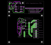
In case I put all supplementary PCBs (Home-Theatre-Bypass, Soft-Power-On, DIL-to-SIL LCD Adapter) on one PCB,
this PCB will cost 5€ as well and will save you 10€ (instead of 3 x 5€ per PCB).
But: Will you be able and cut a PCB (1.6mm FR4, 70µM copper)?
@Impuls: I will think about your suggestion.
(But my current solution won't hurt anyway.)
Best regards - Rudi_Ratlos
Attachments
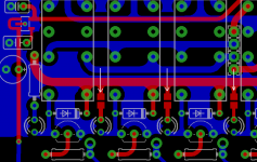
@Impuls: I think that I have got your point and changed the analog-to-digital GND connection like this (white arrow)
Best regards - Rudi_Ratlos
Best regards - Rudi_Ratlos
Attachments
Last edited:
Gentlemen, I have had a nice idea this morning.
In case I put all supplementary PCBs (Home-Theatre-Bypass, Soft-Power-On, DIL-to-SIL LCD Adapter) on one PCB,
this PCB will cost 5€ as well and will save you 10€ (instead of 3 x 5€ per PCB).
But: Will you be able and cut a PCB (1.6mm FR4, 70µM copper)?
@Impuls: I will think about your suggestion.
(But my current solution won't hurt anyway.)
Best regards - Rudi_Ratlos
Good idea, you will need "scored" PCB's. Then you can easily break off the necessary PCB. "Scored" means the PCB is slightly perforated or there is a cut at both sides so the PCB is a bit thinner there. Not enough to break too easily. After breaking it you need to use a file to remove excessive fiber material.
Rudi, I am curious how this version will perform compared with the already existing version. It should be better but the proof is in the eating of the pudding.
Last edited:
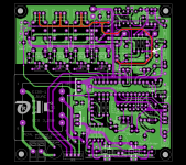
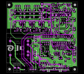
Gentlemen, find attached the final layout of the VCPre - PCB.
I won't do any changes on the layout anymore; the changes are getting too hard to implement.
Before I will open the group-buy, let me tell you another 2 things:
1. The µProcessor communicates with the IR-detector using the RC5 protocol (developed by Philips end of the 1980th.)
It does not understand RC5+, nor does it understand RC6 or any proprietary protocol.
So do not expect the VCpre to understand the protocol that your brand-new Panasonic (or any other brand) handheld transmits to it.
I use an old Philips television handheld (RC437HQN) and it works beautifully.
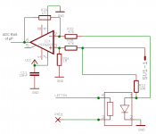
2) I worked very hard on the implementation of the display of the dB-attenuation. I measured the voltage drop across the safety 100 Ohm
resistor on top of the LDR's LED (this resistor prevents you from burning the LED) and built a lookup-table to correlate the attenuation
to the measured voltage drop. I used the input-resistor network of my FC-100 as a load for the serial LDR.
I should have used an instrumentation amplifier (like INA111), but since this type of amplifier is quite expensive and since I am only having
1 power supply voltage (5VDC), I decided to use the MCP6021.
The lookup-table may be rough in your eyes and may not reflect your own setup, but it will give you a "good impression" of the current attenuation.
Best regards - Rudi_Ratlos
I won't do any changes on the layout anymore; the changes are getting too hard to implement.
Before I will open the group-buy, let me tell you another 2 things:
1. The µProcessor communicates with the IR-detector using the RC5 protocol (developed by Philips end of the 1980th.)
It does not understand RC5+, nor does it understand RC6 or any proprietary protocol.
So do not expect the VCpre to understand the protocol that your brand-new Panasonic (or any other brand) handheld transmits to it.
I use an old Philips television handheld (RC437HQN) and it works beautifully.
2) I worked very hard on the implementation of the display of the dB-attenuation. I measured the voltage drop across the safety 100 Ohm
resistor on top of the LDR's LED (this resistor prevents you from burning the LED) and built a lookup-table to correlate the attenuation
to the measured voltage drop. I used the input-resistor network of my FC-100 as a load for the serial LDR.
I should have used an instrumentation amplifier (like INA111), but since this type of amplifier is quite expensive and since I am only having
1 power supply voltage (5VDC), I decided to use the MCP6021.
The lookup-table may be rough in your eyes and may not reflect your own setup, but it will give you a "good impression" of the current attenuation.
Best regards - Rudi_Ratlos
Attachments
The lookup table that Rudi has created doesn't have many steps (not much resolution to show in the LCD) to give a real feeling of the attenuation, the purpose was to show where the pot is, just a rough estimation. I tried using log functions, but apparently the LDR behavior drifts and the values become kinda inaccurate.
Another thing, during the tests I carried out, I noticed that the PIC needs time from the moment supply is connected to it till it actuates the mute relay. I asked Rudi to use n.c. contacts of the mute relay so that actuating the relay means disabling mute, in the past actuating the mute relay meant that mute is enabled, this is far better now, because I can ensure that the amplifier will never see anything other than GND during system startup, for me this is an important aspect.
Another thing, during the tests I carried out, I noticed that the PIC needs time from the moment supply is connected to it till it actuates the mute relay. I asked Rudi to use n.c. contacts of the mute relay so that actuating the relay means disabling mute, in the past actuating the mute relay meant that mute is enabled, this is far better now, because I can ensure that the amplifier will never see anything other than GND during system startup, for me this is an important aspect.
Last edited:
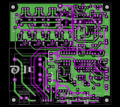
Gentlemen, I have built the BoM for the VCPre - PCB. Find it attached.
Is anybody of you willing to check its completeness?
I will send him the "EAGLE ULP - BoM" to compare. Give me a PM please.
Since I myself have no practice soldering SMD components, but need now, since the VCPre uses the MIC5205 voltage regulator,
I have changed the package of the resistors in front of the relay-status LEDs to "easy to solder "SMD R0805.
These will be the first parts that I will try and solder on the PCB.
Best regards - Rudi_Ratlos
P.S. Sorry: I forgot the leftmost one; of course I will change it as well.
Attachments
Last edited:
Voxxonline: I have only collected the components so far, not the prices.
Shall I guess? 70 - 80€.
Best regards - Rudi_Ratlos
Shall I guess? 70 - 80€.
Best regards - Rudi_Ratlos
Rudi,
You might want to use a larger resistor package, 0805 is very small actually. I think 1206 is excellent and easier to solder.

You might want to use a larger resistor package, 0805 is very small actually. I think 1206 is excellent and easier to solder.
Omar, the 0805 resistor package is an excellent candidate when compared to the SOT-23 package of the MIC5202.
"If I can make it there, I'll make it anywhere" 😀
Best regards - Rudi_Ratlos
"If I can make it there, I'll make it anywhere" 😀
Best regards - Rudi_Ratlos

Rudi if still possible I would add 100nF caps as close as physically possible to output terminal of regulators 7805/06. Always good practice for stability and transient response of regulator to do this. I can see you have one on the 5V rail adjacent to and dedicated to the PIC but another closer to the regulator terminal would be prudent I think.
Gentlemen, I feel happy and respect your requests (see attached image).
But: is there anyone (Wineds?) and complies to my requests as well: "double-check" the BoM, cut the extension PCB and match the SILONEX LDRs?
Best regards - Rudi_Ratlos
Working on it.... Having trouble finding a transformer for US folks. Trying to do it all from Mouser. Hope to have most of it done after work today. Rudi, will you be supplying the per-programmed pic IC?
Billy
@Billyk: I appreciate very much! 🙂
Please give me your EMail_address (via PM) and I will send you the "EAGLE BoM" to double-check.
I am sorry to not being able to provide you a "printed PCB 110VAC primary transformer" / 7-8VAC secondary, rated at about 5VA.
Best regards - Rudi_Ratlos
Please give me your EMail_address (via PM) and I will send you the "EAGLE BoM" to double-check.
I am sorry to not being able to provide you a "printed PCB 110VAC primary transformer" / 7-8VAC secondary, rated at about 5VA.
Best regards - Rudi_Ratlos
Gentlemen, I feel happy and respect your requests (see attached image).
But: is there anyone (Wineds?) and complies to my requests as well: "double-check" the BoM, cut the extension PCB and match the SILONEX LDRs?
Best regards - Rudi_Ratlos
Ok Rudi you want me to match the ldrs? I have done it before when I built a lightspeed. I think I bought about twenty and only got a few good matched sets. I am on the other side of the world to you in case that matters?
Thanks for adding the 100nF caps on the vregs
Last edited:
- Status
- Not open for further replies.
- Home
- Group Buys
- Versatile and comfortable passive pre-amp