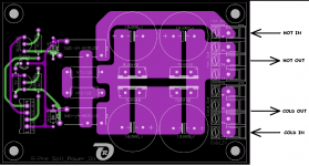
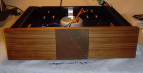
Patrick, the functionality of the "Soft-Power-On" - PCB is very simple.
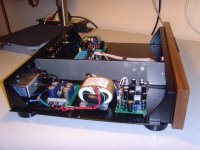
Just have a look at its implementation (image attached, showing the current version with Mains-DC-Filter).
Attach mains' hot and mains' cold to the PCB connectors as shown on the image.
As soon as the top relay closes (the "close-signal" comes from the µP of the VCPre, after a "Resume-from-Standby - command), the mains current flows through the NTCs (the bottom relay is still open!), thus delimiting the inrush current.
After 600ms of delay (as been programmed in the PIC processor) the VCPre sends a signal to close the bottom relay, thus letting the mains current flow unhindered. The status LED will shine then!
I cannot explain better!
Paul: I have never sold (provided) pairs of LDRs with a photocell-resistance as low as 4K! Normal values are between 7 -10K!
The LDR - potentiometer like resistor consist of both the serial-photocell-resistor and the shunt-photocell-resistor as well!
But you have done right ajdusting the LDRs!
I use a LED / resistor connected to 5VDC giving approximately 1.9VDC as input voltage and measure / adjust by means of the provided trim-potentiometer(s).
I have even found (?) a solution on how to provide you a respectable attenuation display by connecting the onboard-MCP6021 OPAMP to the LDR-shunt (!)-resistor and building a lookup-table from the measured values.
Do not think that I have withdrawn from this project!
I have built a very well (!) operating prototype of my pre-amplifier (I call it R-Pre) with a line-buffer in the meantime (see attached image 2) and am currently evaluating it.
Best regards - Rudi_Ratlos
Attachments
Last edited:
Rudi;
For now I will use my soft start.Something else when I turn the volume to the right the sound get lower turn left it gets louder
For now I will use my soft start.Something else when I turn the volume to the right the sound get lower turn left it gets louder
So you have mixed up the connections to the 2-pole motorized-potentiometer power adapter as well!
Just reverse the 2 connections!
Best regards - Rudi
Just reverse the 2 connections!
Best regards - Rudi
Patrick, the functionality of the "Soft-Power-On" - PCB is very simple.
Just have a look at its implementation (image attached, showing the current version with Mains-DC-Filter).
Attach mains' hot and mains' cold to the PCB connectors as shown on the image.
As soon as the top relay closes (the "close-signal" comes from the µP of the VCPre, after a "Resume-from-Standby - command), the mains current flows through the NTCs (the bottom relay is still open!), thus delimiting the inrush current.
After 600ms of delay (as been programmed in the PIC processor) the VCPre sends a signal to close the bottom relay, thus letting the mains current flow unhindered. The status LED will shine then!
I cannot explain better!
Best regards - Rudi_Ratlos
Rudi,
I know but there is now connection at all ,I hear the relais clicking but there is no connection
No power is floating trough the NTC as I turn on the pre amp
So you have mixed up the connections to the 2-pole motorized-potentiometer power adapter as well!
Just reverse the 2 connections!
Best regards - Rudi
When I push the + of the remote it turns right,push - it turns left that has to be like that.
Even when I turn by hand turn left is louder turn right is lower that's not correct
Clockwise is higher volume counter- clockwise lower volume
The jumpers of the potmeter are wrong they need to be mirrored
The jumpers of the potmeter are wrong they need to be mirrored
Since I have finished my VCPre I have always had concerns about the channel balance, Tongiht I verified a very simple way to get the channel balance set precisely.
First make sure the VCpre is operating correctly and is functioning like a potentiometer. Mine emulates a potentiometer of about 4K ohm resistance. Next feed a DC voltage to both L and R inputs simultaneously (I used +5V VA from the VCPre test point but you could easily use a battery as well).
Finally connect one DVM probe to the L OUT and the other to the R OUT. Set the DVM for low mV range (say 200mV FS). Then adjust the balance trimpot for zero. You will find this only holds for one attenuation setting of the VCPre But I found that it held fairly close to zero over the range I listen.
This made a huge difference to the spread and precision of my system sound stage. Very happy with the end result! Thanks once again Rudi for you great work!
So you're saying " if you did a bad job with adjusting the inbalance you could retry by inserting a voltage to the input.Can you tell where to insert the voltage,
VcPre emulates a potentiometre wich is a voltage divider. Try to read about what a voltage divider is and you cam have a better understanding on what Wineds says Voltage divider - Wikipedia, the free encyclopedia
My VcPre perform very well,sound does come like you provide it only thing the potmeter is very sensitive not possible to fine adjusting the control range is too small
Reichelt BOM please check it before order.I will do that too if I find the time
https://secure.reichelt.de/index.html?&ACTION=20&AWKID=762275&PROVID=2084
https://secure.reichelt.de/index.html?&ACTION=20&AWKID=762275&PROVID=2084
Patrick, I am sorry, but I do no longer have a Reichelt-cart for the VCPre.
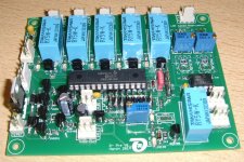
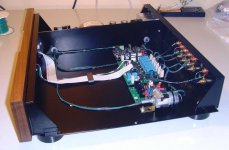
I have been working on the R_Pre (which is the sequel of the VCPre) since some time now (see attached image; the image shows the R_Pre without the LDRs being soldered), and I do share your impression.
This Pre (attenuator) sounds very well, ..., because: "it does not sound at all; it does not have a sound of its own!".
The "LDR - attenuation" does not veil (? - is this the correct translation?) anything, nor does is emphasize anything: it plays the music as it has been recorded!
All of the functionalities of the VC-Pre have been kept (all of its functions can be controlled remotely, has 5 (!) input-sources, has access to unmuted and muted signal, ...) and will be equipped by a very
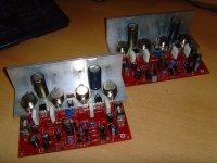
well performing, LM3x7 based tracking-pre-regulator PSU, my version of CALVIN's line buffer (2nd image) ...
I am currently evaluating (a German DIY - friend with very well trained ears! is assisting) the performance of the R-Pre.
Best regards - Rudi_Ratlos
I have been working on the R_Pre (which is the sequel of the VCPre) since some time now (see attached image; the image shows the R_Pre without the LDRs being soldered), and I do share your impression.
This Pre (attenuator) sounds very well, ..., because: "it does not sound at all; it does not have a sound of its own!".
The "LDR - attenuation" does not veil (? - is this the correct translation?) anything, nor does is emphasize anything: it plays the music as it has been recorded!
All of the functionalities of the VC-Pre have been kept (all of its functions can be controlled remotely, has 5 (!) input-sources, has access to unmuted and muted signal, ...) and will be equipped by a very
well performing, LM3x7 based tracking-pre-regulator PSU, my version of CALVIN's line buffer (2nd image) ...
I am currently evaluating (a German DIY - friend with very well trained ears! is assisting) the performance of the R-Pre.
Best regards - Rudi_Ratlos
Attachments
Last edited:
I need to wait for my carpenter-friend's Pre- and Amplifier (dedicated to the red-and-gold TO3-SYMASYM) cases, before I will go on!
Gerhard told me that I will have them before the end of this week!
Best regards - Rudi
Gerhard told me that I will have them before the end of this week!
Best regards - Rudi
Attachments
Rudi,
Nice layout as always one question the LDR's will they be soldered direct to the pcb or will you use separate boards for that?
Nice layout as always one question the LDR's will they be soldered direct to the pcb or will you use separate boards for that?
Great, thanks!
Reichelt BOM please check it before order.I will do that too if I find the time
https://secure.reichelt.de/index.html?&ACTION=20&AWKID=762275&PROVID=2084
Patrick, the LDRs will be soldered on top and below of the 2 blue potentiometers.
Best regards - Rudi
Best regards - Rudi
Rudi, I know but I've seen of someone that also had build a pre with LDR's did use a separate board to solder the LDR this way it was easy to swap the LDR in case they get broken.Don't know anymore where it was
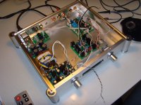
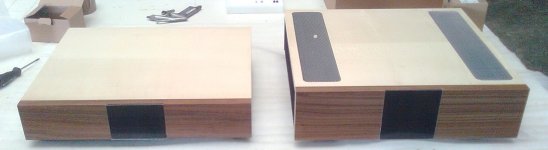
I have completed the build of the PRE in Gerhard's Pre-Amplifier case.
The PRE contains Jean-Paul's DAC, my R-PRE and a line-buffer.
Omar and I are currently working on the replacement of the analog motorized-potentiometer by a digital version (based on MCP4151, followed by a VCCS).
There is still a lot of room in the case, and I am already thinking of installing a RASPBERRY PI with WLAN-connectivity into it as well.
But I will go on and install a TO3-SYMASYM into Gerhard's amplifier-case first.
The quality and "look-and-feel" of his cases are really excellent!
Best regards - Rudi_Ratlos
Attachments

Good morning gents
its been a long time since I had pleasure to visit diyaudio.
My system was left as it is- complex build with pre/dac and filter (similar to yours, Rudi) in "put it back" mode, due to the unclear situation with dac- ws not sure if it works or me connecting something wrong 🙂
Since I have almost no spare time but have desire to listen to the music again (and finally finish system ) I ll ask for some help to put me on a right track.
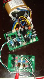
My problem with vcpre as far as I remember is wrong soldering of LDR's top ones are soldered to the bottom and vice versa (shunt and series ?). I remember adjusting vol and putting trimpot in balanced position, but with change in vol - balance was going off.
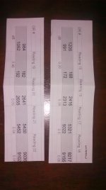
I have attached pic with values of ldrs, if it helps.
I ve seen a method of adjusting balance feeding 5vdc into inputs , will it help to balance it ? I will try it for sure.
It seems better matched ldrs are in the bottom position, thether values of less matched are too off, and I should find another pair to solder ?
its been a long time since I had pleasure to visit diyaudio.
My system was left as it is- complex build with pre/dac and filter (similar to yours, Rudi) in "put it back" mode, due to the unclear situation with dac- ws not sure if it works or me connecting something wrong 🙂
Since I have almost no spare time but have desire to listen to the music again (and finally finish system ) I ll ask for some help to put me on a right track.
My problem with vcpre as far as I remember is wrong soldering of LDR's top ones are soldered to the bottom and vice versa (shunt and series ?). I remember adjusting vol and putting trimpot in balanced position, but with change in vol - balance was going off.
I have attached pic with values of ldrs, if it helps.
I ve seen a method of adjusting balance feeding 5vdc into inputs , will it help to balance it ? I will try it for sure.
It seems better matched ldrs are in the bottom position, thether values of less matched are too off, and I should find another pair to solder ?
Attachments
- Status
- Not open for further replies.
- Home
- Group Buys
- Versatile and comfortable passive pre-amp