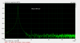
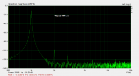
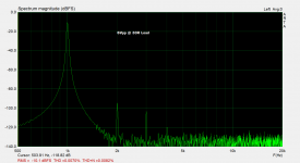
OK. I adapted the power supply rails voltage and the idle current for the headphone use and the measurements improved, as expected. These are the graphs for a 2Vpp amplitude at low 33R load - second harmonic predominant, no raise in distortion with frequency : Tonight I`ll do the listening.
Attachments


This looks great 😀. What transistor are you using for Q3? I see in the pic it's a TO-126 device. BD139?
Sorry, I mixed the marks.. 😁 I'm using KSC2690, KSC3503 is 100mA max. device and shouldn't be used for a headphone amplifier.
Btw, KSC2690 has interesting current gain characteristics, with new japanese devices is mostly flat line. On the graph you could see for KSC2690 the gain rises with current so it's kind of self compensating as I see it, higher the current, higher the gain.
Attachments

I've listened to it and can't find a thing to complain about, it sounds very good I couldn't find the difference compared to TPA6120a2. Anyway for me, main purpose will be the line amplifier and I hope I'll have a chance to compare it with commercial products in the future,,,
Cheers, Borko.
Cheers, Borko.
Hi Bogdan,
You made me curious about your project and I would like to try it, being passionate about listening to headphones.
Given that PCB files and other details are available, I would be grateful if you could provide them to me.
Thank you in advance.
You made me curious about your project and I would like to try it, being passionate about listening to headphones.
Given that PCB files and other details are available, I would be grateful if you could provide them to me.
Thank you in advance.
Hi Bogdan,
You made me curious about your project and I would like to try it, being passionate about listening to headphones.
Given that PCB files and other details are available, I would be grateful if you could provide them to me.
Thank you in advance.
Ok, no problem, but in a few days when I have some time to edit few small errors I had on the pcb.
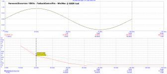
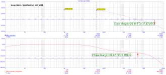
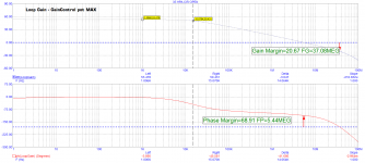
Something from the simulations, the following is FFT of 1Vpeak 10KHz at 600R load for FeedbackControlPot Min and Max positions and how it affects the loop gain. As you can see it`s adjusted to 10x ratio.
Attachments
Haha, I came up with small modification, that gives 10 times less distortion 😀 .
For now, approved in spice, tomorrow I'll do the real life measurements.
For now, approved in spice, tomorrow I'll do the real life measurements.

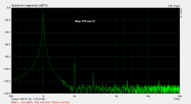

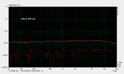
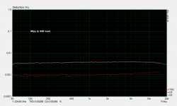
This is the new set of measurements for 33R load of the Version 2. These measurements are done with power supply configured to +/-15V and the bias is 83mA. With higher rails and higher idle current the results could be even better if needed. Tomorrow the PCB file will be ready. 😉
Cheers, Borko.
Cheers, Borko.
Attachments
Is there a way to set operating points and/or output devices for 5w into 32ohms with less than 0.05% THD and dominant 2nd order?
Is there a way to set operating points and/or output devices for 5w into 32ohms with less than 0.05% THD and dominant 2nd order?
I could try in simulation, why 5W into 32 Ohms, any example?
PCB File
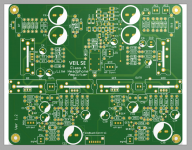
This is the render of the finall PCB file. Anyone who wants to try it, send me an email in pm. PCB is two layer, 166 x 137mm.
Heatsinks are Ficher SK-104-25, for higher bias version, SK-104-38 or SK-104-50, should be used.
This is the render of the finall PCB file. Anyone who wants to try it, send me an email in pm. PCB is two layer, 166 x 137mm.
Heatsinks are Ficher SK-104-25, for higher bias version, SK-104-38 or SK-104-50, should be used.
Attachments

Last edited:


I could try in simulation, why 5W into 32 Ohms, any example?
Some very inefficient but well regarded planar magnetic cans like HE-6...
It could be done, but iit's a extreme case..that would dissipate lot more heat, this is a sepp output stage with maximum 2 x idle current.
- Home
- Amplifiers
- Headphone Systems
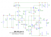
- VEIL SE Line / Headphone CFB amplifier