VEIL SE Class A - Line / Headphone CFB amplifier
Intro:
Veil SE is a line / headphone amplifier with available real time harmonic content adjustment. It`s a minimalistic topology, class A amplifier capable of driving all kinds of headphone loads, with low default distortion that can be adjusted to higher levels via the pot on the front panel.
Topology and description of operation:
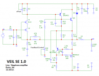
The amplifier consists of only two stages working in “current feedback” configuration. Input stage is a cascoded, common source jfet, coupled to bjt compound feedback pair output stage, with no degeneration. Output stage is working in single ended mode, loaded with the variant of “mu follower” acting as variable current source, so the maximum output current is twice the value of the amplifiers output stage idle current. The “feedback control” pot is used to manipulate the gain of the output stage cfp. Semiconductors used are commonly used and available. It`s everything on one PCB, from power supply rectifiers, to fixed voltage capacitance multipliers and output relay circuit with turn on delay and output DC protection. The preamp is DC coupled from input to output with protection relay not in the signal path.
The circuit is easily adjustable for different idle currents and could be configured to work with max +/-35V DC, if it`s used as a voltage gain stage for power follower amps, like First Watt F4 or anything similar...
Subjective sound impressions:
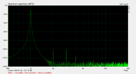
This is the best preamplifier ever 😀 ! Just kidding, I`ll do the tests in a few weeks when chassis is done… This is a result of extensive experiments with this kind of not so common topology and I tweeked the circuit for the best measurement results I could get.
Later I`ll send the schematic with real measurement graphs. Simulation results are pretty similar btw.
Cheers!
Intro:
Veil SE is a line / headphone amplifier with available real time harmonic content adjustment. It`s a minimalistic topology, class A amplifier capable of driving all kinds of headphone loads, with low default distortion that can be adjusted to higher levels via the pot on the front panel.
Topology and description of operation:
The amplifier consists of only two stages working in “current feedback” configuration. Input stage is a cascoded, common source jfet, coupled to bjt compound feedback pair output stage, with no degeneration. Output stage is working in single ended mode, loaded with the variant of “mu follower” acting as variable current source, so the maximum output current is twice the value of the amplifiers output stage idle current. The “feedback control” pot is used to manipulate the gain of the output stage cfp. Semiconductors used are commonly used and available. It`s everything on one PCB, from power supply rectifiers, to fixed voltage capacitance multipliers and output relay circuit with turn on delay and output DC protection. The preamp is DC coupled from input to output with protection relay not in the signal path.
The circuit is easily adjustable for different idle currents and could be configured to work with max +/-35V DC, if it`s used as a voltage gain stage for power follower amps, like First Watt F4 or anything similar...
Subjective sound impressions:
This is the best preamplifier ever 😀 ! Just kidding, I`ll do the tests in a few weeks when chassis is done… This is a result of extensive experiments with this kind of not so common topology and I tweeked the circuit for the best measurement results I could get.
Later I`ll send the schematic with real measurement graphs. Simulation results are pretty similar btw.
Cheers!
Attachments

Last edited:
Thread moved to Headphone Systems
Sorry,for some reason I can`t edit the thread name mistake, it`s VEIL... 😀
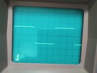
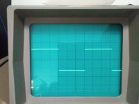
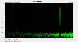
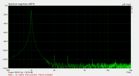
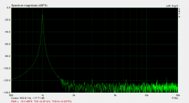
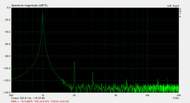
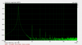
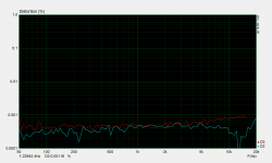
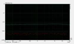
So, here`s the circuit and IMD graphs for 5K and 47R load :
Attachments

Last edited:
Compensation
During the experiments, I got to this type of compensation idea, and I don't remember I saw it anywhere, so no idea what to call it, but works very well in this application. It's some kind of "bootstraped" Miller compensation and it is also semi output inclusive. When compared to classic Miller compensation, it requires smaller value of capacitor, for the same feedback loop bandwidth and imo that is a plus.
During the experiments, I got to this type of compensation idea, and I don't remember I saw it anywhere, so no idea what to call it, but works very well in this application. It's some kind of "bootstraped" Miller compensation and it is also semi output inclusive. When compared to classic Miller compensation, it requires smaller value of capacitor, for the same feedback loop bandwidth and imo that is a plus.

Very nice circuit! The measured data looks great too.
Can we please see this preamp with +/-20V (40Vpp) into a circa 10k ohm load? That’s what is needed for 25wrms into 8ohms from say, an F4 or other 0dB gain power output stage.
Can we please see this preamp with +/-20V (40Vpp) into a circa 10k ohm load? That’s what is needed for 25wrms into 8ohms from say, an F4 or other 0dB gain power output stage.
Last edited:
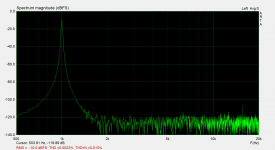
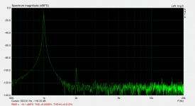
Thanks xrk971. Ok, for the measurement you want I neeed +/-24V rails to do it properly, but, for a quick test, near that range, this is measured with +/-21V rails and the amplitude is 36Vpp at 5K load. Btw to be able to do this measurement I had to raise the gain (lower value for R4-47R).
Attachments
Btw the circuit is quite flexible and this configuration at the moment is probably not adequate for such requirement. Besides the power supply rails, idle current is about 65mA right now, so I guess lowering it, one could find the sweet spot, that would also benefit performance.
Never the less I think it preforms very well in terms of measurement for a such low part count, 2 stage amplifier...
Cheers, Borko.
Never the less I think it preforms very well in terms of measurement for a such low part count, 2 stage amplifier...
Cheers, Borko.
Thank you for running the test so quickly. That looks very good. I believe Hugh Dean’s Aksa Lender preamp’s output stage also has a CCS and BJT with a mu-follower. I found this to work very well at driving lower impedance loads while keeping distortion at reasonable levels. I am surprised that the H3 rose a bit above the H2 given that it is SE Class A and a singleton input stage. But still excellent looking result and very clean sounding I bet. Nice work!
Last edited:
H3 is begining to rise when gets close to rails (clippiing territory) it should be lower with little higher rail voltages. I guess the mu follower is helping in decreasing 2nd harmonic, due to the "push pull" operation and level of second harmonic is easily adjusted for the taste with the "feedback control" pot on the front panel (look at short video attached on the first page).
This looks great 😀. What transistor are you using for Q3? I see in the pic it's a TO-126 device. BD139?
This looks great 😀. What transistor are you using for Q3? I see in the pic it's a TO-126 device. BD139?
It's KSC3503, didn't tried but I think BD139, MJE340 or something similar could be used.
Good stuff. TTC004B is probably worth a try as well. What value did you settle on for R3?
Sorry I'll update missing parts in the schematic later, R3 is 1K8 and J2 could be 2sk3557 or any available, higher transconductance, smd nch jfet that is available, I made it with 2sk932 with no noise problems in this case.
- Home
- Amplifiers
- Headphone Systems
- VEIL SE Line / Headphone CFB amplifier