Interested in the various ways there are whereby one can generate a negative voltage within a given tube amp design. The more legit, the better. This is asked in the context of avoiding having to install an additional AC line step down tranny. I'm also assuming "flea power", in the single digit mA or so.
I've tried a voltage doubler off an unused 6.3V heater winding. With a slight load to enable an adjustment pot, it barely gets up the -10V needed for a 6BQ5 P-P design. (Next up to bat is a voltage triple-er)
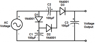
I've seen an RCA design where a capacitor connects to one side of the B+ tranny winding, followed by a resistor to ground. Then to the cathode of a diode, then cap to ground.
Other ideas?
I've tried a voltage doubler off an unused 6.3V heater winding. With a slight load to enable an adjustment pot, it barely gets up the -10V needed for a 6BQ5 P-P design. (Next up to bat is a voltage triple-er)
I've seen an RCA design where a capacitor connects to one side of the B+ tranny winding, followed by a resistor to ground. Then to the cathode of a diode, then cap to ground.
Other ideas?

That is similar to what I use. I use a 2uF film cap off one leg of the B+ to generate the negative bias supply. Low current so it works. It does produce a slight DC offset to the transformer current though.
Rectifying the output of an oscillator might work if you only need a few ma for a bias voltage.
Win W5JAG
Win W5JAG
Are you modifying an existing machine, or do you have complete design freedom? An existing machine will have B+ suitable for the 6BQ5s plus cathode resistors, possibly too much without the loss from the original cathode resistors, especially for vintage stuff designed for lower AC line voltages and for superior output valves, easily and cheaply available at the time.
A slightly lossy, but bullet-proof option is to float the negative end of your B+ supply maybe 20 Volts below signal ground. Some combination of parallel resistor and Zener diode sits between the HV windings' center tap plus first B+ capacitor's negative terminal and signal ground, and this point, after filtering, is your -20 VDC bias supply. The resistor and/or Zener must pass all the amp's DC, so it's somewhat lossy, but no obvious failure mode could damage the output stage. Just like a common cathode resistor would act.
Also, I'm very surprised that you'd get such a low output from unloaded 6.3 VAC doubler. You'd expect maybe 15 VDC?
All good fortune,
Chris
If using an old transformer which is used with a tube rectifier, just use solid state diodes to make a negative HT rail. OK its a lot of volts but for making a negative bias not much current required.
An example of that can be found here:Rectifying the output of an oscillator might work if you only need a few ma for a bias voltage.
Win W5JAG
Post #16
As it is, I'm modifying, so it's more like being boxed in a maze than complete design freedom. One situation (where the voltage doubler is barely working for 6BQ5s) is there is no existing cathode resistor, it was a cheapo charlie. So I thought I could flip it into a fixed bias, by generating a -15V rail. I have one 6.3V heater winding to work with and the PT doesnt have a center tap - it's a voltage doubler. Voltage across the tubes goes up 33V, in losing all those filaments their cathodes dropped across, with a 400V B+. It's not UL, so I understand I can drop the screens down 100V from the plate voltage and maybe still get a reliable amp.
Another amp has two spare windings, I believe both are 6.3, but that one uses 6V6s which need more negative bias, at least double; the challenge with what I have to work with fits like a glove. That one also has all 4 tubes across one cathode resistor...which I also figured I could somehow flip into fixed bias.
In the hunt for a solution, I connected a 600 Ohm to 600 Ohm audio transformer across a 6.3V power winding and got 6.3 on the other side. With the current being a fraction of a mA, it may work to double the input to a voltage doubler. I left it on for an hour with zero perceptible heating in the little tranny - at no load. I guess that just shows I'm struggling to find a workable solution, with some adjustment margin.
Maybe I just give up and buy some resistors instead... I do like the idea of being able to adjust the bias. I also understand fixed bias has advantages, like if done right, you never have to worry about it again.
Thanks for the insights!
From the Guitar amp design book:
IF using a centertapped HV winding transformer, with centertap grounded, just use a resistive attenuator as needed from one of the AC taps to ground and rectify that with a single diode, oriented to get negative voltage as needed.
Say you have a 300+300VAC trafo, connect a 100k>10k attenuator to one of the 300VAC taps , you get 30VAC, rectify that for about minus 40/42Vdc
Scale up/down as needed.
If using a single HV winding feeding a bridge, no part of it ever gets negative, so you separate one end from the +DC component using a capacitor which also works as a lossless Voltage attenuator, fed a grounded resistor and rectify voltage developed across it.
Yo will need a very good capacitor, often "X" rated ones are used there.
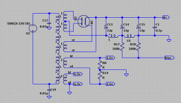
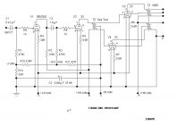
Example: what Marshall does on some of its amps:
C15-R7 are the voltage attenuator and DC component remover, D1 - C14 rectify negative DC for bias, extra resistors, capacitor and trimmer adjust and filter it.
Production wise, much cheaper/faster than winding an extra bias tap.
IF using a centertapped HV winding transformer, with centertap grounded, just use a resistive attenuator as needed from one of the AC taps to ground and rectify that with a single diode, oriented to get negative voltage as needed.
Say you have a 300+300VAC trafo, connect a 100k>10k attenuator to one of the 300VAC taps , you get 30VAC, rectify that for about minus 40/42Vdc
Scale up/down as needed.
If using a single HV winding feeding a bridge, no part of it ever gets negative, so you separate one end from the +DC component using a capacitor which also works as a lossless Voltage attenuator, fed a grounded resistor and rectify voltage developed across it.
Yo will need a very good capacitor, often "X" rated ones are used there.
Example: what Marshall does on some of its amps:
C15-R7 are the voltage attenuator and DC component remover, D1 - C14 rectify negative DC for bias, extra resistors, capacitor and trimmer adjust and filter it.
Production wise, much cheaper/faster than winding an extra bias tap.
"As it is, I'm modifying, so it's more like being boxed in a maze than complete design freedom. One situation (where the voltage doubler is barely working for 6BQ5s) is there is no existing cathode resistor, it was a cheapo charlie. So I thought I could flip it into a fixed bias, by generating a -15V rail. I have one 6.3V heater winding to work with and the PT doesnt have a center tap - it's a voltage doubler. Voltage across the tubes goes up 33V, in losing all those filaments their cathodes dropped across, with a 400V B+. It's not UL, so I understand I can drop the screens down 100V from the plate voltage and maybe still get a reliable amp."
So, this is a vintage amp with the combined 150mA of the four output valves heating the phono input 12AX7s and such? Folks like to rag on this, but I think it's brilliant - highly filtered 150mA of DC wasn't an easy thing before silicon rectifiers. An elegant modern improvement is to add small current sensing resistors, maybe 10R each, into each cathode line, and to leave the rest of the cathode circuit alone, (except maybe install a much, much larger bypass cap. You might even want a Zener across that as safety backup).
Then, grid bias for each 6BQ5 can come from a series of fixed resistors and a trimpot, from the common cathode point to signal ground. And cathode current can be sensed from the small, maybe 10R, cathode resistors.
Your second amp is the same case as a Dyna SCA-35 and others of it's era. It would benefit from the same treatment, with the common cathode resistor somewhat increased for larger adjustment range, or even Full Monty, with input stages heated by the output stages' combined cathode currents.
All good fortune,
Chris
You can use mixed bias (fixed and cathode), small resistor in the cathodes to make up the rest of the voltage, and still have adjustable bias. A small (12V or more) transformer in reverse connected to a 5V or 6.3V winding can give 50VAC or so. I've used the capacitor/resistor divider from plate supply AC as well.
I have a board that uses a SMPS (flyback) to generate -60V fed from a doubler off the 6.3VAC winding.
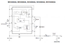
Another option up to about -30V is a MC34063 in inverting boost configuration, see the datasheet.
Another option up to about -30V is a MC34063 in inverting boost configuration, see the datasheet.
Also, I'm very surprised that you'd get such a low output from unloaded 6.3 VAC doubler. You'd expect maybe 15 VDC?
All good fortune,
Chris
My 5vac tap was unused due to SS rectifier- voltage tripled it and got no load 19vdc w/ circuit below. 5k trim pot to gnd for some load.
Jim
Attachments
If you're going the switching route I would just buy a ready made module like this https://www.digikey.com/en/products/detail/cui-inc/PSK-3D-12/13922513
Interesting that it will take in AC and even DC up to 430 volts. Can't go wrong for $6. Add a 100uH choke and maybe 22uF cap and you should have a pretty clean output.
Interesting that it will take in AC and even DC up to 430 volts. Can't go wrong for $6. Add a 100uH choke and maybe 22uF cap and you should have a pretty clean output.
use this circuit
Has worked for thousands of amplifiers. There is an alternate which uses a cap as the big dropper. It may have quirks but Marshall made a million of them.
No, you have to check and adjust whenever you change tubes. (Or just cold-bias and cross your fingers; millions of guitar amps did.)fixed bias has advantages, like if done right, you never have to worry about it again.
Cathode bias splits the difference between a boogie tube and the tube in the socket so is less likely to get way far out. And a resistor is MUCH less liable to go astray than clever rectifiers and inverters.
The more legit, the better.
What are ill-legit plans? Endangered electric eels? Mercury batteries?
Do a hunt for "Back Biasing" on the internet.
It's how negative voltages were always generated previously.
It's how negative voltages were always generated previously.
That was a very common solution used in 30s & early 40s domestic receivers. It was called back biasThis is how my 1936 Paillard radio does it. In the radio it is the loudspeaker field coil, but just the R of a CR filter should be the same I would have thought.
since the negative volts were most often used to bias the output tube, by then usually a pentode.
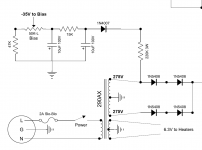
Back bias still works today, here it is in a PP 33 amp, all 2V filamentary tubes.
The bias network is R10, R11, R12 & C3.
This project was published in Glass Audio Projects Book, Summer 2002.
Attachments

- Home
- Amplifiers
- Tubes / Valves
- Various ways to generate NEGATIVE voltages used in Tube Amplifiers