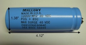
Mallory 12,000 uF 30V
These are the caps I used.
spec sheet says 0.018 ohm ESR and 8.4A max ripple current.
I use 3 sets of 2 series caps.
I realize I do not need so much voltage, but I get them new for $4 CAD each and I have lots of space so they are a nice solid package and the system is dead quiet and sounds great. 🙂
These are the caps I used.
spec sheet says 0.018 ohm ESR and 8.4A max ripple current.
I use 3 sets of 2 series caps.
I realize I do not need so much voltage, but I get them new for $4 CAD each and I have lots of space so they are a nice solid package and the system is dead quiet and sounds great. 🙂
Attachments
Last edited:
with a little bit of arithmetic, have modeled the effect.
.
Thanks AndrewT. I appreciate you showing me the modeling. I will spend some time to digest it, but thanks for showing the way
Hello Guys
I'm about try a dc blocked on my amp it has a 500va toroidal trans.
what you guys think about this cap : PEG226HJ4330QE1 Kemet | 399-7548-ND | DigiKey
two in parallel should be ok for a 15 amps of my power outlet.
Thanks
I'm about try a dc blocked on my amp it has a 500va toroidal trans.
what you guys think about this cap : PEG226HJ4330QE1 Kemet | 399-7548-ND | DigiKey
two in parallel should be ok for a 15 amps of my power outlet.
Thanks
Hello Guys
I'm about try a dc blocked on my amp it has a 500va toroidal trans.
what you guys think about this cap : PEG226HJ4330QE1 Kemet | 399-7548-ND | DigiKey
two in parallel should be ok for a 15 amps of my power outlet.
Thanks
At about $9 each, this is expensive and may be overkill. You are undoubtedly paying for the 150C temp rating.
Cheers,
Bob
These are the caps I used.
spec sheet says 0.018 ohm ESR and 8.4A max ripple current.
I use 3 sets of 2 series caps.
I realize I do not need so much voltage, but I get them new for $4 CAD each and I have lots of space so they are a nice solid package and the system is dead quiet and sounds great. 🙂
Where you did buy yr cap for $4 cad. ?
Thanks
Hi Guys
I follow this thread from start because I plan to build DC Blocker. I have on shelf diodes like: DHG30I600HA IXYS - High Performance Fast Recovery, Low Loss and Soft Recovery Single Diode. How do you think: they are useful instead standard diode or I will get worst effect using fast recovery diodes?
Thanks
Janusz
Hi Guys
I follow this thread from start because I plan to build DC Blocker. I have on shelf diodes like: DHG30I600HA IXYS - High Performance Fast Recovery, Low Loss and Soft Recovery Single Diode. How do you think: they are useful instead standard diode or I will get worst effect using fast recovery diodes?
Thanks
Janusz
No need for fast/soft recovery in this application. Ideally they almost never conduct. Just use reliable high-current bridge rectifiers.
Cheers,
Bob
brunogiovs
Toronto, see this site. Bottom of page. Now listed for $3. I think it is $4 on the shelf. He always has a large box on hand.
Capacitor-Capxon
Toronto, see this site. Bottom of page. Now listed for $3. I think it is $4 on the shelf. He always has a large box on hand.
Capacitor-Capxon
overload and start up and other abnormally high currents use the bypass route around the capacitors.The Bryston 4BSST uses two 33,000uF, 6.3V polarized capacitors connected in parallel in opposing directions across the blocking diodes. They use a high-current bridge rectifier to implement the blocking diodes.
Most of the time the capacitors will be conducting high-current spikes of relatively low duty cycle, as is normal for rectifier circuits, as opposed to sinusoidal current.
Inrush current at turn-on may be stressful to these circuits, so it might be a good idea to employ a soft-start circuit.
Cheers,
Bob
That's the purpose of the diodes. To by pass the capacitors.
A secondary purpose is to limit the capacitor voltage so that reverse voltage across the DC block does not damage the capacitor, but the DC blocker should not operate "normally" in this bypass mode. The peak voltage across the capacitors should be less than the turn on voltage of the diodes for effective DC blocking action.
Ideally they almost never conduct.
Last edited:
The Crown circuit does not include any capacitors.
It cannot operate as a DC blocking circuit.
Do the calculation for the first level simplification model of the impedance of the 3300uF capacitor. And then try passing 15Apk across a pair of them.Hello Guys
I'm about try a dc blocked on my amp it has a 500va toroidal trans.
what you guys think about this cap : PEG226HJ4330QE1 Kemet | 399-7548-ND | DigiKey
two in parallel should be ok for a 15 amps of my power outlet.
Thanks
The Crown circuit does not include any capacitors.
It cannot operate as a DC blocking circuit.
I'm not sure I agree. Don't get me wrong, I think the capacitors should be there. However, a couple tenths of a volt DC around zero will be blocked by the rectifier, just in not a "nice" way, since the diodes will always be going in and out of conduction at every zero crossing of the mains.
That having been said, some dc offset in the mains may affect the waveform symmetry after the diodes so as to "pass" some average dc on to the transformer. I'm just not sure.
Bottom line, I think it is wrong to make the generalization that the Crown circuit cannot operate as a dc blocking circuit. BTW, for what other reason would they incorporate those diodes?
Cheers,
Bob
I will make the generalisation.
It is the accumulation of asymmetric waveform that builds up an excess of flux in one direction that leads to the saturation or near saturation of the core.
That accumulation could occur in a few dozen cycles and one hears the growl of the excess current in the one direction. During the next few cycles that excess one direction flux could all be canceled. The growl disappears.
The core just waits for the next flux build up. In the same direction as the last or in the opposite direction. We hear the growl.
This is why we hear the growl build and disappear repeatedly. It is rarely constant.
Now inserting a pair of inverse parallel diodes does not stop the asymmetry of the mains waveform. It does not stop the near saturation of the core as the flux builds up excessively in one direction.
The capacitor seems to stop the accumulation of excess flux and thus stops the growl.
The only thing I can think of that does similar is a differentiating opamp. It is the opposite of an integrating opamp which adds to the output offset as the inputs ADD to the previous signal.
The DC blocked transformer behaves like a differentiating opamp, whereas the non DC blocked transformer increases in flux as the error accumulates like an integrator.
Could you explain why the added capacitor changes the action and allows the flux to remain near neutral over the full cycle of an asymmetric waveform?
Last edited:

I will make the generalisation.
It is the accumulation of asymmetric waveform that builds up an excess of flux in one direction that leads to the saturation or near saturation of the core.
That accumulation could occur in a few dozen cycles and one hears the growl of the excess current in the one direction. During the next few cycles that excess one direction flux could all be canceled. The growl disappears.
The core just waits for the next flux build up. In the same direction as the last or in the opposite direction. We hear the growl.
This is why we hear the growl build and disappear repeatedly. It is rarely constant.
Now inserting a pair of inverse parallel diodes does not stop the asymmetry of the mains waveform. It does not stop the near saturation of the core as the flux builds up excessively in one direction.
The capacitor seems to stop the accumulation of excess flux and thus stops the growl.
The only thing I can think of that does similar is a differentiating opamp. It is the opposite of an integrating opamp which adds to the output offset as the inputs ADD to the previous signal.
The DC blocked transformer behaves like a differentiating opamp, whereas the non DC blocked transformer increases in flux as the error accumulates like an integrator.
Could you explain why the added capacitor changes the action and allows the flux to remain near neutral over the full cycle of an asymmetric waveform?
Average dc cannot pass through a capacitor.
As I indicated with my caveat above, what you are saying about the asymmetry of the waveform causing some net dc-like flux even after the diodes may be true. But one needs to evaluate the magnitude of that effect as compared to the effect without diodes. I don't know the answer, but I don't think hand-waiving adequately address the question.
Once again, I ask why Crown would be using the diodes if it did not make significant improvement to the dc situation? They are smart people.
Cheers,
Bob
Hint: capacitors are very good at integrating (=~accumulating) currents into voltages. In fact, that's the way they are mathematically defined: Capacitor - Wikipedia, the free encyclopediaThe capacitor seems to stop the accumulation of excess flux and thus stops the growl.
2nd hint: the flux in a core is proportional to the integral of the voltage driving it.
Finally, a transformer of any kind acts as an absolute blocker for DC, from primary to secondary quite obviously, but also in the opposite direction: even the crudest of halfwave rectifier after a transformer will draw a (distorted, OK) balanced current on the primary, and no series capacitor will improve on something that is already perfect to begin with...
Hint: capacitors are very good at integrating (=~accumulating) currents into voltages. In fact, that's the way they are mathematically defined: Capacitor - Wikipedia, the free encyclopedia
2nd hint: the flux in a core is proportional to the integral of the voltage driving it.
Finally, a transformer of any kind acts as an absolute blocker for DC, from primary to secondary quite obviously, but also in the opposite direction: even the crudest of halfwave rectifier after a transformer will draw a (distorted, OK) balanced current on the primary, and no series capacitor will improve on something that is already perfect to begin with...
With all respect, do you think the guys posting above don't know this? Besides, it's way off what's being discused. I think you are completely missing the point.
........................
Could you explain why the added capacitor changes the action and allows the flux to remain near neutral over the full cycle of an asymmetric waveform?
I don't see how your explanation helps me to understand why the growl we hear, stops, when the excess flux builds up in one direction.Hint: capacitors are very good at integrating (=~accumulating) currents into voltages. In fact, that's the way they are mathematically defined: Capacitor - Wikipedia, the free encyclopedia
2nd hint: the flux in a core is proportional to the integral of the voltage driving it.
Finally, a transformer of any kind acts as an absolute blocker for DC, from primary to secondary quite obviously, but also in the opposite direction: even the crudest of halfwave rectifier after a transformer will draw a (distorted, OK) balanced current on the primary, and no series capacitor will improve on something that is already perfect to begin with...
First note that asymmetry per se is not problematic: it's the non-zero average value that causes the growling. It can exist at the primary or the secondary, and it has to be tackled locally: by including a filter at the primary and properly matching the diodes at the secondary (in theory, it would be possible to compensate the DC flux from one winding by an opposite flux from another one, but not in this context).
In the primary filter, a capacitor works by blocking the DC, but as I said the core also has integrating properties. When it is associated with a high value resistance (like diodes below the conduction threshold), it will have a similar blocking effect: the unwanted DC voltage will appear as a non-zero average across the diodes (provided this average is insufficient to make the diodes conduct significantly).
This means the diodes alone can play the role of the capacitor, but as Bob remarked, this will result in ugly waveforms.
This URL don't goes open. is this the same than the upload from post #3 about this thread? - go to
http://www.diyaudio.com/forums/powe...t-buzzing-toroid-transformers-what-right.html
or post #19 about
http://www.diyaudio.com/forums/powe...buzzing-toroid-transformers-what-right-2.html
the currently version looks like a version with two diodes in a TO220 outline and two serial electrolytics in opposite to the previous version with one zener-/supperssor diode and one electrolytic cap - go toAfter looking the different topologies again (attachement post # 1), I discover for me the Var. VII
from LC Technology about
L C Audio Technology / DC Filter
as my currently favourite.
At first look I had overlooked that the Zener diode is actually a bidirectional diode - at reverse mode like a normal diode (0V7 voltage loss). Who can upload the schematic of LC's currently danish version?
Because the DC component from mains always have one direction, I can try to put in the main plug in reverse polarity if buzzing effects don't go away (unfortunately this isn't perform in all countries - independend of the kind of the mains plug).
In one of this two directions I get a DC filtering with max 4V3 and in the other one of 0V7.
Thus the solution from LC Technology is a good solution at least here in Germany because the mains connector polarity isn't defined.
http://web.archive.org/web/20111118111344/http://www.lcaudio.com/index.php?page=316
the currently URL unfortunately don't show the schematic:
http://www.lcaudio.com/index.php?page=316
Last edited:
- Home
- Amplifiers
- Power Supplies
- Variations of DC Main Filter against buzzing Toroid Transformers - what is the right?