I understand the objection and the need for long integration periods. If we were only considering the very non-linear crossover region it would still be hard to right any wrong there. However, when operating class A and with bias currents peaking to 1,2 amps or so in the linear region and always beyond the minimum class A requirement, can appreciable bias distortion still be generated?
Let me just suggest Gareth's 200 mA bias as a minimum bias level for discussion.
Let me just suggest Gareth's 200 mA bias as a minimum bias level for discussion.
Last edited:
Hi Ian,
Dumb question: I've difficulties to understand precisely what kind of circuit and/or what kind of bias control mechanism you have in mind. Would you elaborate on this, please?
Dumb question: I've difficulties to understand precisely what kind of circuit and/or what kind of bias control mechanism you have in mind. Would you elaborate on this, please?
OK, you are not the first to say that, you know.
I am trying though, to sketch a simple model Lin dual-rail amplifier that will start as unbiased, traditionally named B class SS amplifier. Let's make it medium power, BJT and EF output topology. From there we can install any type of bias mechanism that permits stable operation of the amplifier.
We have discussed in general terms, quite a few schemes for controlling bias in AB and A amps but Bigun has revised his list of requirements (post 35) which seem to reduce the list to just the known methods of reducing dissipation in class A designs!
That is how I understand the progress to date. Please correct me If I'm wrong.
The Krell bias method for class A operation of the output stage is one that seems possibly suitable. I don't know the schematic well at all, much less how one should go about implementing it but I'm sure we would all like to get an amp. operating in class A with less heat, just like anyone else here.
There are, hopefully, other methods that should and probably will be be considered more carefully, even if they are not fundamentally A class. I would like to consider class "XD" as means of skirting the bias adjustment problem altogether, if that's not an oxymoron.
Member
Joined 2009
Paid Member
It would be great if you can help me find a good topology for this, I have grand plans ! My real plan is to make a hybrid amplifier with tube front end and SS back end using some kind of sliding biass Class A for the best performance with low(ish) power dissipation.
But you guys might have some other interests here and it would be presumptuous to assume this thread should be restricted to my personal goals so feel free to expand on things... perhaps we can refine the goals to suit everyone ??
We certainly don't want to restrict ourselves to known methods, this is DIY afterall (Destroy It Yourself 😀)
Err...Tube front end amp did you say? Klystron or Trivista hehe!
Seriously, that is no easy consideration in view of feedback requirements. The goal I appreciate but I wouldn't dive into that for an evening's entertainment. Masochist!
OTOH...There are a couple of common cathode twin triodes that might be interesting as a differential amp....Have tube manual?
Seriously, that is no easy consideration in view of feedback requirements. The goal I appreciate but I wouldn't dive into that for an evening's entertainment. Masochist!
OTOH...There are a couple of common cathode twin triodes that might be interesting as a differential amp....Have tube manual?
Last edited:
Member
Joined 2009
Paid Member
I'm not looking to employ feedback, a tube front end to act as a voltage amp and a SS output with some kind of sliding biass to act as the current amp.
Tubes are a new world to me. I have a few lying around and even some Nuvistors. But I need to 'pay my dues' to the tube god and build something traditional first (http://www.diyaudio.com/forums/tubes-valves/167872-my-cellini-triode-amp.html)
I am thinking of a hybrid with a relatively simple front end, perhaps just a choke loaded 6SN7. But that's for another day. In the meantime, I need a SS output structure that's as clean as possible so that I can get away with no feedback. I don't care for concerns about damping factor. How do we make a SS output structure which looks and sounds like Class A, but warms up like a Class B ????
Bigun, I think you should go over the renardson amp design again, the feedforward does work to reduce the crossover distortion, one of the halves dont need to be biased in class A. Have a look at the last incarnation, at lower levels his amp has no higher harmonics than 2nds and the total THD is incredibly low for such a simple design.
With the use of just 2 diodes and two resistors you could experiment and lower crossover distortion to a degree and then decide if such a scheme is really worth it, have a look at ostrippers amp design thread.
With the use of just 2 diodes and two resistors you could experiment and lower crossover distortion to a degree and then decide if such a scheme is really worth it, have a look at ostrippers amp design thread.
So how does Krell's stepped bias sit with that problem, other than by making far fewer but incremental changes to the bias? Presumably it just anticipates the power envelope and applies sufficient class A bias to keep beyond AB threshold and avoids further error.
Hello Ian
Have you ever done actual measurements on a real Krell using stepped bias technique and measured amplifiers THD performance.
Regards
Arthur
Free lunch biasing
Have you ever done actual measurements on a real Krell using stepped bias technique and measured amplifiers THD performance. [/QUOTE said:Hi Phoenix,
No, hence the question but this was actually posted by Sebastiaan (#12). In his absence also, perhaps you would like to expand on the THD issue and comment on the suitability, or not, of Krell's bias system, for this task here of low dissipation class A.
I can't see such a bias control mechanism on the schematics of the smaller models posted elsewhere on forum. Being unsure of these, perhaps we shouldn't consider KSA 50 and smaller. I'd like to be wrong about that actually.
Member
Joined 2009
Paid Member
Bigun, I think you should go over the renardson amp design again, the feedforward does work to reduce the crossover distortion, one of the halves dont need to be biased in class A.
This is what I read on his website at: Amplifier Variations.
"The problem is that we require the top half to remain conducting in class-A at all times so that it can act as a feedforward error amplifier and cancel the effect of the lower half switching off over part of the signal cycle."
😕
Feedback? I'm with Gareth, feedback between SS output stage and tube is probably not needed. The big question is the choice of OPS topology.
Member
Joined 2009
Paid Member
Hugh - I agree, it would seem a shame to use gnf with a linear triode up-front but some folk can't sleep without a damping factor and an amp with flat well defined gain curve!
Anyhow, I'm trying to narrow down the field for OPS topology to look at in more depth that hold out some hope of having some evidence of low distortion due to their biassing - at least until I see more deserving candidates, to the following short list:
Steven Dunlap's KRILL - which appears to have a biassing set-up that isn't really 'variable bias' but it "lets the air out" of the transistor turning off so gently as to be benign in terms of higher order harmonics.
Nelson Pass - dynamic bias patents
Hawksford Error Correction - doesn't really look like variable biass Class A but I suspect it holds out some useful ideas
Allison-Kean - looks very promising, although Keantoken tells me it favours relatively high bias
BotchUp Diamond - I am still playing with the Diamond Buffer (also used in Pete Millet Max amplifiers) there are some ideas 'out there' on the web for 'auto bias' that I will look into
Steve Dunlap alludes to the diamond buffer structure of the Krill OPS. Perhaps he would care to comment or make suggestions. This could be well be helpful in narrowing the field a bit.
Member
Joined 2009
Paid Member
Steve Dunlap alludes to the diamond buffer structure of the Krill OPS. Perhaps he would care to comment or make suggestions. This could be well be helpful in narrowing the field a bit.
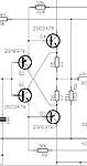
Yes, Juma posted this schematic in the Krill thread (attached)
The diamond buffer has a fancy name, but it's really just an arrangement of EFs. Broskie has recycled a few of these ideas in his blogs - his Triadtron starts off with what I and others on this forum have been called a "JLH buffer", although he doesn't use that term and then onto the Taylor topology - lots of fun with only 3 or 4 devices, reminds me of Kenpeters' and my own thoughts this past few months - but the Triadtron auto-bias falls short of what we're looking for here.
There is also the Accuphase version which allows the first pair of devices to establish bias (2nd attachment) which looks promising.
Attachments
"The problem is that we require the top half to remain conducting in class-A at all times so that it can act as a feedforward error amplifier and cancel the effect of the lower half switching off over part of the signal cycle."
😕
It strikes me that this argument would apply to a push-pull
Class AB as well. When one side shuts down, the other is
already in conduction, and is capable of correcting error.
😎
Member
Joined 2009
Paid Member
It strikes me that this argument would apply to a push-pull
Class AB as well. When one side shuts down, the other is
already in conduction, and is capable of correcting error.
😎
so....I need to stop thinking of this as asymmetrical

Another candidate here ?
http://www.triadaudio.net/Triad_Aud...asing Boost with Enhanced Current Mirrors.pdf
Gareth,
I'm partial to the diamond buffer, as are many.
Why don't you lash one up and try it open loop?
I recommend MJE15030/31 as drivers, btw, with high bias. Try to avoid using a bias generator between the bases of the drivers, that is, join them together.
Hugh
I'm partial to the diamond buffer, as are many.
Why don't you lash one up and try it open loop?
I recommend MJE15030/31 as drivers, btw, with high bias. Try to avoid using a bias generator between the bases of the drivers, that is, join them together.
Hugh
Member
Joined 2009
Paid Member
Hi Hugh - yes I would like to, I've never heard this topology. I have a bunch of 5200 & their compliment in my 'junk box' so I'd likely start with those. How does the MJE compare ?
But my tendency to simulate for 'ages' before I build anything is not actually what's holding me back this time - I am in the process of building a Single Ended Triode amplifier so whilst that happens on the workbench my brain is looking at DB's....
How would you compare 1) OL DB against 2) 'regular' EF type II with gnf ? (hope that question isn't too heavy on the acronyms!)
DB is better than EF2 in my opinion, about the same then a properly implemented triple stage.
Renardson uses bias currenty of 100 ma for his feedforward scheme, thats normal class AB biasing current, you have to go through his designs procedures to understand how his scheme works, I take my hat off for the guy, getting the THD figures he does with his latest design is impressive.
Renardson uses bias currenty of 100 ma for his feedforward scheme, thats normal class AB biasing current, you have to go through his designs procedures to understand how his scheme works, I take my hat off for the guy, getting the THD figures he does with his latest design is impressive.
Even through I have been "ghosting" this site for a while , E Stuart's bias control is the first cool thing 🙂 I've seen in a while.
As well as drooling over his active bias page , I see Van de Gevel's original from which ES derived his improved version. Valve and transistor audio amplifiers - Google Books
This is very worthy of simulation and protoyping since the whole circuit could be made VERY small (I do SMD now) and could just be a "drop in" replacement (don't have to "tear up" any existing amp) for any VBE on a small SMD "daughtercard". Since I use BJT's and high rails , I guess this will have to be ported to my use.
I am very curious to see this circuits effect on Xover and total THD.
OS
Last edited:
- Status
- Not open for further replies.
- Home
- Amplifiers
- Solid State
- Variable operating biass output ?