
Hi again Felipe
Just went back a page & saw your bild pics...
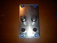
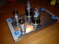
...cool...nice ventilation.
Good sturdy rack-mount job !
No wooden sides to catch fire !
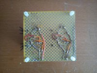
Your reg-board looks like it's made on board with a diagonal hole pattern.
Never seen that before.
Whats the under-side copper pattern on it ?
Cheers
Si.
Just went back a page & saw your bild pics...
...cool...nice ventilation.
Good sturdy rack-mount job !
No wooden sides to catch fire !
Your reg-board looks like it's made on board with a diagonal hole pattern.
Never seen that before.
Whats the under-side copper pattern on it ?
Cheers
Si.
How much current in total draws the Valve Itch to calculate the dummy load or wich value have I to use as dummy load)
How much current in total draws the Valve Itch to calculate the dummy load or wich value have I to use as dummy load)
The two 6N2P's draw about 1.4mA per side and the two 6SN7's about 4mA per side, so 10.8mA total. A 27Kohm 10 watt resistor would draw just over 11mA.
Are you using only two half valves per channel (half 6N2PEV+half 6SN7)?
I explaint better:
One channel
V1 half valve 6N2PEV one triode
V3 half valve 6N2PEV one triode of the other valve
V2 half valve 6SN7 one triode
V4 half valve 6SN7 one trione of the other valve
I think is the only way to connect the heaters and elevate V3 & V4
I explaint better:
One channel
V1 half valve 6N2PEV one triode
V3 half valve 6N2PEV one triode of the other valve
V2 half valve 6SN7 one triode
V4 half valve 6SN7 one trione of the other valve
I think is the only way to connect the heaters and elevate V3 & V4
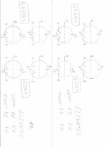
The way it was made as in the original schematics is two bottles you elevate two bottles you don't. They get separate heater power LM317 branches. Then you use the elevated group for the top parts of the mu followers between channels. Only the non elevated group's heaters see ground.
I don't understand your schematic, I see only tubes, no heater connections. There are the shared schematics that show exactly.
- Home
- Source & Line
- Analogue Source
- Valve Itch phono