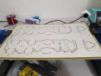
That looks great! I should have gone with the pin headers like you did with the plastic guide (eg P7). I've attached a picture of my filter board, there's not much around the unused pins.
What case are you going to use? I'm still looking around and haven't decided if I'm going to put the transformers and PSU boards in a separate case yet.
What case are you going to use? I'm still looking around and haven't decided if I'm going to put the transformers and PSU boards in a separate case yet.
Attachments
Last edited:
Thanks Sonny, your filter pcb looks the same as the ones I have here...not a lot of metal for the solder to cling to.
Regarding the case, I always make my own from scratch, that way I get the industrial look I am after and everything fits and functions just as it should. A lot of work though. Digging through my parts on the weekend I found some really nice Amphenol circular connectors so am now pretty sure I will go straight for the two box solution. Thinking forward if the ValveDac functions and sounds like it should then I may even experiment with a LCLC power supply rather than the standard CRCRC and will definitely need to keep those chokes in another case. I really like that Marcel has opted for an unregulated B- power supply and the caps I have selected for it will be equally useful in the LCLC variant as well.
Regarding the case, I always make my own from scratch, that way I get the industrial look I am after and everything fits and functions just as it should. A lot of work though. Digging through my parts on the weekend I found some really nice Amphenol circular connectors so am now pretty sure I will go straight for the two box solution. Thinking forward if the ValveDac functions and sounds like it should then I may even experiment with a LCLC power supply rather than the standard CRCRC and will definitely need to keep those chokes in another case. I really like that Marcel has opted for an unregulated B- power supply and the caps I have selected for it will be equally useful in the LCLC variant as well.
Trying to round out my parts list. I have the FPGA on order, toroidal transformers and Jensens coming, and got the rest of the tubes. I think all that is left is to get the inputs and AC inlet.
What connects to P9? I looked at the schematic and still couldn't figure it out. Would that be where an I2S source would connect? If so, how would you select that with the input switch?
What connects to P9? I looked at the schematic and still couldn't figure it out. Would that be where an I2S source would connect? If so, how would you select that with the input switch?
Originally, when I drew the schematic and designed the PCB, P9 was an extension connector with no specific purpose. Later randytsuch asked me to add an I2S input and I used P9 for that. It is explained on the downloads section of the Linear Audio website, "Design data package for Marcel van de Gevel's Valve DAC from Vol 13":
P9 pin 1: sel4192in, 0 selects the I2S (or raw DSD) input, 1 selects the DIX4192 S/PDIF interface. Debounced input with internal pull-up that can be connected to a fifth contact of the source selection switch.
P9 pin 3: mutei2sin, 1 mutes the sound when it comes from the I2S input.
P9 pin 5: datai2sin, I2S audio data input or raw DSD left audio data input.
P9 pin 7: deemni2sin, low level activates 50 us/15 us de-emphasis when the I2S input is active.
P9 pin 9: bcki2sin, bit clock for the I2S or raw DSD input.
P9 pin 11: lrcki2sin, word clock for the I2S input or right channel raw DSD data.
P9 pin 13: dsd64_128, must be 0 for DSD64 and 1 for DSD128 when the raw DSD interface is used.
P9 pin 15: dsdon, must be 0 for PCM or DoP, 1 for raw DSD.
P9 pins 2, 4, 6, 8, 10, 12, 14, 16: ground
P9 pins 17, 18, 19, 20: 3.3 V supply pins, see the schematic.
All inputs have internal pull-ups except dsdon and dsd64_128, which have internal pull-downs. The extension connector can be left unconnected when the I2S input isn't needed. The logic high level is nominally 3.3 V.
You need version 2.1 of the configuration file for the I2S input to work.
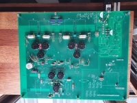
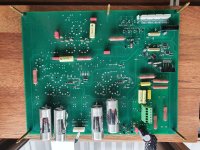
Two days of soldering and everything is populated apart from a handful of power supply caps that are yet to arrive. Went a bit stupid ordering resistors but in the pre and power amps I've built any resistor or capacitor on the grid/anode/cathode of the valve makes a difference to the sound and I have no reason to believe it would be any different in the ValveDAC.
Have put any of the taller through-hole components underneath the pcb so I can maximise the height of the valves protruding from the top of the case. Basically started with the necessary parts such as the trimpots and anything taller had to go down below.
I'm sorry I have to write this, but putting through-hole parts on the bottom side may or may not worsen crosstalk between the digital and analogue/mixed-signal parts of the design and affect the noise floor. It depends on what parts and how close they get to the digital sections. For example, I don't expect any problems when the big DC blocking capacitors are on the back side, as Ray mounted them, but I'm not so sure about the 1.82 kohm tail resistors, particularly of the right channel.
In any case, I have no way to predict how big this effect is, so it could very well be that it works just fine like you mounted it.
Glad you pointed that out Marcel, because I was not sure. Trivial to swap those resistors back to the top side which I will do. Is there anything else that looks dodgy in terms of placement?
I'll have a closer look this evening Dutch time (it's 9:24 AM here now and I have to work).
Last edited:
After more reading, I think I'm going to implement either an Amanero or I2SoverUSB. I2SoverUSB I would need a separate 5V supply though unless I wanted to rely on USB power.
Amanero needs that too for best audible performance. There is a mod to run it from clean power.
Once powered sorta similarly, IMHO I2SoverUSB clocks sound better.
Both Amanero and I2SoverUSB give the best results with external clocking, where the clock is located right next to the dac chip or other location that will be to most beneficial effect. And of course, if the clocking implementation is well designed.
Last edited:
SonnyMarrow is building an original valve DAC, where the signal first goes into an FPGA module, then into an asynchronous sample rate converter, then back into the FPGA module, then gets reclocked twice by flip-flops and then gets retimed by a current-steering valve logic gate. The incoming I2S bit and word clock shouldn't be too critical with such a set-up - at least any phase noise outside the asynchronous sample rate converter's bandwidth is suppressed.
It's different for the raw DSD valve DAC, there the clock that comes in via the raw DSD interface drives the DAC core with nothing in between that could suppress any jitter/phase noise.
It's different for the raw DSD valve DAC, there the clock that comes in via the raw DSD interface drives the DAC core with nothing in between that could suppress any jitter/phase noise.
Amanero needs that too for best audible performance. There is a mod to run it from clean power.
Once powered sorta similarly, IMHO I2SoverUSB clocks sound better.
Both Amanero and I2SoverUSB give the best results with external clocking, where the clock is located right next to the dac chip or other location that will be to most beneficial effect. And of course, if the clocking implementation is well designed.
Thanks for the response, I've seen your name in some of the threads I've found on i2s stuff. Do you have a preferred USB to i2s solution? Right now I'm between the I2SoverUSB and the WaveIO. There are a couple at diyinhk that look interesting, but I'm not sure if I trust the support, drivers, etc. I've seen great things about the WaveIO support.
Last edited:
Glad you pointed that out Marcel, because I was not sure. Trivial to swap those resistors back to the top side which I will do. Is there anything else that looks dodgy in terms of placement?
Besides the 1.82 kohm tail resistors, I recommend also moving R23, R24, R6, R15, C33, C26, R77, R101, C48, R86, R102 and C55 back to the top.
Sonny, I purchased the I2SoverUSB3 from JLSounds. This is the card that is being back-fitted into the Lampizator dacs at the moment as an improvement to the Amanero. Like Marcel says though, it likely doesn't matter much in this particular dac, but if you are like me you might want to be sure...
If you use two power supplies on the JLSounds card it becomes galvanically isolated, and this may or may not be something that is useful for the ValveDac or perhaps your playback system in general. Personally, I would prefer to keep my music server on a different mains loop than my playback system, so galvanic isolation may be helpful.
If you use two power supplies on the JLSounds card it becomes galvanically isolated, and this may or may not be something that is useful for the ValveDac or perhaps your playback system in general. Personally, I would prefer to keep my music server on a different mains loop than my playback system, so galvanic isolation may be helpful.
Alright, I think I'll get that and forego the oscillator board. I'll use two separate PSUs for it.
I'm still trying to decide my PSU layout. My current plan is that all transformers, the -300V Maida, the 6.3VDC PSU for tubes, and a 6VDC Sigma 11 will be in a second enclosure. From the PSU enclosure, an 8-pin umbilical to the DAC: 2 for 300VDC, 2 for 6.3VDC, 2 for 6.3VAC, possibly 2 for 6VDC to go to the various 5VDC supplies needed for the USB solution.
I'm still trying to decide my PSU layout. My current plan is that all transformers, the -300V Maida, the 6.3VDC PSU for tubes, and a 6VDC Sigma 11 will be in a second enclosure. From the PSU enclosure, an 8-pin umbilical to the DAC: 2 for 300VDC, 2 for 6.3VDC, 2 for 6.3VAC, possibly 2 for 6VDC to go to the various 5VDC supplies needed for the USB solution.
Last edited:
You will also need a wire or two in there to connect the chassis ground of the two boxes together for safety. And then if it was me at least another couple of pins spare just in case.
I may end up doing a single-enclosure setup for convenience. I really wanted to avoid having any AC in the umbilical by replacing the Valve DAC's 5V supply, but then saw it needs the 6.3VAC to go to R107 and R108. At that point, not worth replacing the on-board 5V since the 6.3VAC needs to go to the main board anyway.
Do you have a preferred USB to i2s solution? .
I use I2SoverUSB for my own AK4499 dac project. It needs one clean power supply to run. With that it will always be galvanically isolated. It can use two clean power supplies isolated from each other as sort of a belt and suspenders approach to isolation. One supply is fine in most cases.
Last edited:
Can the 6.3VAC that goes to R107 and R108 be replaced in any way? That's my last obstacle to keeping all AC stuff in a separate box.
- Home
- Source & Line
- Digital Line Level
- Valve DAC from Linear Audio volume 13