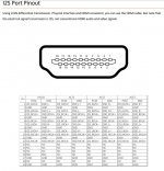
That Audiophile style article was a little misleading as regards the pinout.
I2S enhanced, as it was originally known, does not use unused pins. It uses the same pins as HDMI. There is no compatibility between the two.The manufacturers can use any pins not used by the HDMI standard in the connector for the I2S interface.
Attachments
Thanks, pity that there are four permutations in use... Do you know what RSV stands for?
On the white I2S connector shown on a photograph in the article about the interface box, there is a signal D_ON which presumably indicates that it is DSD. Is there an equivalent for the LVDS I2S/raw DSD connection?
On the white I2S connector shown on a photograph in the article about the interface box, there is a signal D_ON which presumably indicates that it is DSD. Is there an equivalent for the LVDS I2S/raw DSD connection?
Last edited:
My mistake. The first diagram is from Holo Audio not Denafrips. RSV seems to be unique to them and there is no reference to it in the manual (Holo Audio May dac). The other pins vary depending on the vendor but haven't seen anything dedicated to indicating I2S.
This is painful to read. Getting DSD out of a DVDP or BDP player is a big deal. Suggest more reading time.
3. It would therefore be handy if a circuit that switches various I2S signals to the single I2S input of the DAC supported raw DSD, 3.3 V CMOS and LVDS levels.
I'm trying to come up with a circuit with four inputs that fulfills the requirements of point 3. It will consist of a couple of three-state buffers and LVDS receivers with three-state outputs and some glue logic.
Not sure if you have had a look but does this board tick those boxes? Possibly not...
It has no LVDS inputs, otherwise it does. The Chinese interface also appears to have 3.3 V CMOS outputs (the white connector), so I don't know if you really need LVDS.
I was thinking about something where you can just use a single eight-position source select switch to switch between optical, three times S/PDIF or AES3 and four I2S/raw DSD inputs. With this board you would end up with a five-position switch that switches between optical, three times S/PDIF or AES3 and I2S/raw DSD and then a separate push-button to select one of four I2S/raw DSD sources.
I was thinking about something where you can just use a single eight-position source select switch to switch between optical, three times S/PDIF or AES3 and four I2S/raw DSD inputs. With this board you would end up with a five-position switch that switches between optical, three times S/PDIF or AES3 and I2S/raw DSD and then a separate push-button to select one of four I2S/raw DSD sources.
Hi Marcel, have you ever thought, if available, to implement LEDs or a display for reading the input signals and formats?
Hi Marcel, have you ever thought, if available, to implement LEDs or a display for reading the input signals and formats?
You can find usb to i2s modules that offer support for such features.
Hi Marcel, have you ever thought, if available, to implement LEDs or a display for reading the input signals and formats?
When I thought about the user interface, I had a temporary obsession with the life and work of Alan Turing. I considered implementing a Pilot ACE emulator as a softcore microcontroller with the remaining FPGA resources and using that to make a nice user interface with an alphanumeric display and everything (no punched card reader, though).
I soon realized that doing so would mean at least another year of spending most of my spare time writing and debugging Verilog code and writing Pilot ACE machine language. I decided that I did not really want that and that it was time to snap out of Aspie++ mode. Hence the decision to just make a very basic interface with a few knobs and lamps.
You could decide to do what I didn't, though. As long as you come up with a user interface that needs no more than the 23 FPGA I/Os that I use for my knobs and lamps, you can just remove the neon lamp and switch interface circuits (ZTX558-circuits for the neon lamps and 330 ohm-1 nF low-pass filters for the switches) and connect the I/Os to whatever you want to connect them to. You can then modify the Verilog code and use the remaining FPGA resources to implement your user interface, either directly with state machines or via a softcore microcontroller. My Verilog code is available on Downloads | Linear Audio and everyone is very welcome to modify it as they like.
By the way, for debugging purposes, I sent signals to user LEDs on the FPGA module that indicate that the sampling rate is greater than 90 kHz, 100 kHz and 190 kHz. To be precise, there is a little hysteresis and the actual thresholds are:
90 kHz and 90.98567818 kHz
98.991750687 kHz and 100 kHz
189.973614776 kHz and 190.98143236 kHz
It would be quite straightforward to send those signals to three of the neon lamps. If you don't want to use the surprise mode, it only requires a change in the user constraints file and going through the steps of the FPGA synthesis process. If you do want to use the surprise mode, it is a very minor change to the Verilog code and going through all the steps of the FPGA synthesis process.
Gosh Marcel, next you'll be designing a Colossus DAC. 🙂
Tommy Flowers's Colossus was a special-purpose computer meant specifically for cracking Lorenz SZ-40 and SZ-42 ciphers, while the ACE computers were Turing's design of a universal Turing-complete stored-program computer. The Pilot ACE was actually a simplified version of Turing's 1945 design.
Gosh Marcel, next you'll be designing a Colossus DAC. 🙂
So long as there isn't a Guardian DAC.
Tommy Flowers's Colossus was a special-purpose computer meant specifically for cracking Lorenz SZ-40 and SZ-42 ciphers, while the ACE computers were Turing's design of a universal Turing-complete stored-program computer. The Pilot ACE was actually a simplified version of Turing's 1945 design.
Yes, I was being rather tongue in cheek Marcel. Anyway, my listening room wouldn't be big enough...
- Home
- Source & Line
- Digital Line Level
- Valve DAC from Linear Audio volume 13