Thanks, Ray. Paid for. I've no objection to that. I'd send one of the spare boards to Marcel as a gratitude for his wonderful design. With a board on hands, maybe it'd be easier for him to help us along the builds later on. 🙂That cost is based on ordering 20 PCBs. That means we will have 2 spare PCBs so can I make a suggestion regarding them. As the full cost of the 20 PCBs will be covered by your payments, I will hold the spare PCBs and if someone requires one later I will sell at £26.50 and donate the proceeds to DIY Audio. Does anyone object to that?
Good to hear that, Marcel. What'd be the Vrms I could expect out of these transformers' balanced outputs? Modern DACs seem to have 4Vrms as a standard now.I'm sure it is. With a circuit like in post #215, connect pins 3 and 4 to each other and to R2. Short pins 9 and 10. Connect L1-C2-R1 to pin 1, connect L4-C6-R4 to pin 6, connect pin 7 to R3 and connect pin 12 to C9.
The only thing is that the values of R3 and C9 are optimized for the Lundahl transformer, so you may have to tweak them to get the flattest possible response. If you could find a datasheet or application note for your transformer, it may already specify the optimal values.
About 1 V RMS, in fact 1.24 V if the transformer had no insertion loss. See post #575 for more information.
Last edited:
I'd send one of the spare boards to Marcel as a gratitude for his wonderful design. With a board on hands, maybe it'd be easier for him to help us along the builds later on. 🙂
Cheers. Marcel already has a standing offer for a spare PCB from Dan and my original order but he's happy with his original build.
I've already received a number of deposits - thank you.
We're Rolling!
First orders have been placed.
I have just ordered from JLCPCB;
Now I have the hard costs for them I'll update my spreadsheet later this evening to attribute the costs depending on what subscribers have signed up for.
I'm ready to pull the trigger on the main PCB order as soon as I get sufficient deposits to cover the costs.
BTW, one thing I forgot regarding the costs for the PCBs is to remind everyone that I may get hit by import duty so the cost may rise again. We'll see but it's not something I can manage away so we'll just have to live with it.
NB: Just had a message to say the JLCPCB order has been accepted and is already in their production flowline.
First orders have been placed.
I have just ordered from JLCPCB;
- 50 Reconstruction Filter PCBs from (order qty jumped from 30 to 50 - we needed 32!)
- SMD solder stencils
Now I have the hard costs for them I'll update my spreadsheet later this evening to attribute the costs depending on what subscribers have signed up for.
I'm ready to pull the trigger on the main PCB order as soon as I get sufficient deposits to cover the costs.
BTW, one thing I forgot regarding the costs for the PCBs is to remind everyone that I may get hit by import duty so the cost may rise again. We'll see but it's not something I can manage away so we'll just have to live with it.
NB: Just had a message to say the JLCPCB order has been accepted and is already in their production flowline.
Last edited:
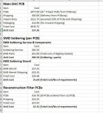
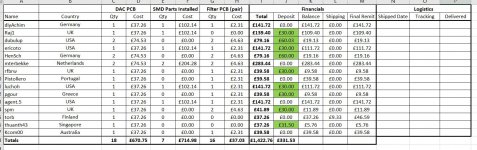
GB Costings
Now that I've placed the first orders I have some firm costs and I've also made some assumptions to hopefully get somewhere close to the final costs. I've attached an excerpt from my spreadsheet showing my workings on the costs. For the Reconstruction Filters and SMD Soldering, short of some unforeseen surprises I thing the costings are complete. For the main PCB I have made some 'negative' assumptions to try and give a picture of the potential final costs, such as factoring in having to pay import duty and the cost of delivery from PCBway.
Anyway, take a look and please ask any questions you may have.
Ray
Attachments
Having received some more deposits overnight, this morning I have placed the order for the main DAC PCBs. Shipping was a little less than I had estimated (£44 vs £50) so the unit cost of the PCBs has dropped by a small amount.
The production and shipping schedule suggests that I will receive the PCBs around mid-September. I will send my spare PCB on to torb in the next day or two (and replace it when the 20 arrive) so we'll hopefully have another build underway before too long.
We just have to wait now. I think the only other item I have outstanding is to check and publish the BOM/Dgikey Basket for the through-hole components I used for my build - I will try to get that done over the weekend. Anything else you chaps need?
I'm just waiting on the last few deposits;
Attachments

Mr. nautibuoy, when you connect the PPY reclocker to the valve dac, where do pin 5 DSD2 and pin 3 DSD1 go? Which one is left to P4 DSDLA and which one is right to p7 DSDRA?
Hi Agent.5. Both the reclocker and Valve DAC boards have 'Amanero pattern' headers so I just plugged them together, paying attention to orientation/alignment of course. Does that answer your question?
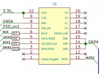
Matching the pin outs of the connector, it appears that DSD1 is connected to DSDLA and DSD2 is connected to DSDRA.
I've attached screengrabs from the schematics (yellow=reclocker, white=Valve DAC). It's slightly confusing because the header numbering is different on the two but if you renumber one or the other it'll all fall into place.
I installed my BBB/reclocker combo under the Valve DAC board, positioned so that the Valve DAC plugs straight onto the reclocker header (you just need to experiment to get the relative heights of the standoffs right). I have a mechanical drawing with the drill holes for both the Valve DAC and BBB stand-off drill holes correctly positioned if that would help?
I installed my BBB/reclocker combo under the Valve DAC board, positioned so that the Valve DAC plugs straight onto the reclocker header (you just need to experiment to get the relative heights of the standoffs right). I have a mechanical drawing with the drill holes for both the Valve DAC and BBB stand-off drill holes correctly positioned if that would help?
Attachments

Last edited:


The first Valve DAC GB PCB (my spare from the original purchase) is on its way to torb in Finland today.
Also, I've had an enquiry from a potential late arrival GB subscriber - if they follow up on their interest everyone will see a small reduction in the unit costs of the PCBs - I will post an update if it happens.
I've received deposits from everyone (except for one subscriber who made me aware that he's away until early September) so all good. Thanks everyone.
Last edited:
I've attached screengrabs from the schematics (yellow=reclocker, white=Valve DAC). It's slightly confusing because the header numbering is different on the two but if you renumber one or the other it'll all fall into place.
I installed my BBB/reclocker combo under the Valve DAC board, positioned so that the Valve DAC plugs straight onto the reclocker header (you just need to experiment to get the relative heights of the standoffs right). I have a mechanical drawing with the drill holes for both the Valve DAC and BBB stand-off drill holes correctly positioned if that would help?
It looks like I messed up with the DSD64_128 and FS0...FS3 pins. They are grounded now, which doesn't matter when you use the reclocker, but matters when you connect an Amanero Combo384. A workaround is to remove these pins from the header.
According to https://www.amanero.com/drivers/combo384-D.pdf , DSD64_128 is open drain, so grounding it does no harm. That still leaves FS0...FS3.
Maybe I used this datasheet by mistake, which has them all NC: https://www.amanero.com/drivers/combo384-D3.pdf
Last edited:
- Home
- Source & Line
- Digital Line Level
- Valve DAC from Linear Audio volume 13