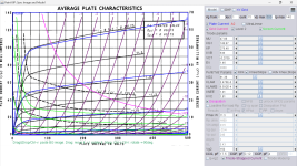
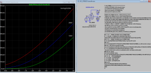
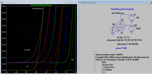
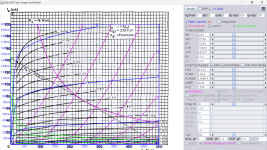
Here is updated version of 12GN7A using the current paint tool. If you wish to compare there is also Ayumi model find in the archie. Post comment to this forum for any error.
Code:
**** 12GN7 ******************************************
* Created on 03/17/2023 13:39 using paint_kip.jar
* www.dmitrynizh.com/tubeparams_image.htm
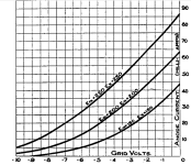
* Plate Curves image file: 12gn7.png
* Data source link: <plate curves URL>
*----------------------------------------------------------------------------------
.SUBCKT 12GN7 P G2 G K ; LTSpice tetrode.asy pinout
* .SUBCKT 12GN7 P G K G2 ; Koren Pentode Pspice pinout
+ PARAMS: MU=47.88 KG1=148.87 KP=278.48 KVB=536 VCT=-0.2709 EX=1.46 KG2=81.38 KNEE=1.01 KVC=1.81
+ KLAM=3.476E-6 KLAMG=6.592E-4 KNEE2=22.14 KNEX=3.698 KNK=0.008664 KNG=0.03125 KNPL=4.386E-6 KNSL=0.000907 KNPR=122.97 KNSR=95.14
+ CCG=17.5P CGP=0.12P CCP=4P VGOFF=-0.6 IGA=0.001 IGB=0.3 IGC=8 IGEX=2
* Vp_MAX=500 Ip_MAX=140 Vg_step=1 Vg_start=0 Vg_count=15
* X_MIN=56 Y_MIN=31 X_SIZE=754 Y_SIZE=531 FSZ_X=1296 FSZ_Y=736 XYGrid=false
* Rp=1600 Vg_ac=23.5 P_max=11.5 Vg_qui=-23.4 Vp_qui=240
* showLoadLine=n showIp=y isDHP=n isPP=n isAsymPP=n isUL=n showDissipLimit=y
* showIg1=y isInputSnapped=n addLocalNFB=n
* XYProjections=n harmonicPlot=y dissipPlot=n
* UL=0.43 EG2=150 gridLevel2=y addKink=y isTanhKnee=y advSigmoid=n
*----------------------------------------------------------------------------------
RE1 7 0 1G ; DUMMY SO NODE 7 HAS 2 CONNECTIONS
E1 7 0 VALUE= ; E1 BREAKS UP LONG EQUATION FOR G1.
+{V(G2,K)/KP*LOG(1+EXP((1/MU+(VCT+V(G,K))/SQRT(KVB+V(G2,K)*V(G2,K)))*KP))}
RE2 6 0 1G ; DUMMY SO NODE 6 HAS 2 CONNECTIONS
E2 6 0 VALUE={(PWR(V(7),EX)+PWRS(V(7),EX))} ; Kg1 times KIT current
RE21 21 0 1
E21 21 0 VALUE={V(6)/KG1*ATAN((V(P,K)+KNEX)/KNEE)*TANH(V(P,K)/KNEE2)} ; Ip with knee but no slope and no kink
RE22 22 0 1 ; E22: kink curr deviation for plate
E22 22 0 VALUE={V(21)*LIMIT(KNK-V(G,K)*KNG,0,0.3)*(-ATAN((V(P,K)-KNPL)/KNSL)+ATAN((V(P,K)-KNPR)/KNSR))}
G1 P K VALUE={V(21)*(1+KLAMG*V(P,K))+KLAM*V(P,K) + V(22)}
* Alexander Gurskii screen current, see audioXpress 2/2011, with slope and kink added
RE43 43 K 1G ; Dummy
E43 43 G2 VALUE={0} ; Dummy
G2 43 K VALUE={V(6)/KG2*(KVC-ATAN((V(P,K)+KNEX)/KNEE)*TANH(V(P,K)/KNEE2))/(1+KLAMG*V(P,K))-V(22)}
RCP P K 1G ; FOR CONVERGENCE
C1 K G {CCG} ; CATHODE-GRID 1
C2 G P {CGP} ; GRID 1-PLATE
C3 K P {CCP} ; CATHODE-PLATE
RE23 G 0 1G
GG G K VALUE={(IGA+IGB/(IGC+V(P,K)))*(MU/KG1)*
+(PWR(V(G,K)-VGOFF,IGEX)+PWRS(V(G,K)-VGOFF,IGEX))}
.ENDS
*$Attachments
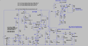
Here is a schematic of a 12GN7 PP amp that you might want to verify the model with.
https://www.doc88.com/p-5999581472181.html
https://www.doc88.com/p-5999581472181.html
Attachments

Thanks, Koonw, for all of the models that you take the time to create and post.
I'm curious about the how the Ayumi models compare against those created from tools like paint, particularly any differences that might affect simulation accuracy. Do you have any insights that you can share? Adrian, you might be able to comment on this too.
I'm curious about the how the Ayumi models compare against those created from tools like paint, particularly any differences that might affect simulation accuracy. Do you have any insights that you can share? Adrian, you might be able to comment on this too.
I have been testing 12GN7s in a driver for the 300B.
A test of 50 tubes from various manufacturers gives anywhere from 0.5%thd to 4%thd at 50Vrms out Triode wired in a Hybrid Mu follower circuit. Mu ranged from 26.8 to 45 with one outlier at 54.
The Ayumi model gives roughly 0.086% thd with a gain of 37.76
Your model gives roughly 1.61% thd with a gain of 33.79
I can provide the .asc if desired.
Attachments
Thanks. The .asc file would be interesting. But it looks like both models are very optimistic as to THD. I've always tended to be skeptical of simulation THD figures anyway and now I know why. 😉

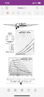
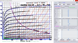
Try this AC2_PENDD Mazda pentode model (capacitances probably need adjusted):
Code:
**** AC2_PENDD ******************************************
* Created on 03/18/2023 12:46 using paint_kip.jar
* www.dmitrynizh.com/tubeparams_image.htm
* Plate Curves image file: AC2-PENDD.png
* Data source link: <plate curves URL>
*----------------------------------------------------------------------------------
.SUBCKT AC2_PENDD P G2 G K ; LTSpice tetrode.asy pinout
* .SUBCKT AC2_PENDD P G K G2 ; Koren Pentode Pspice pinout
+ PARAMS: MU=27.49 KG1=645.29 KP=141.22 KVB=6942.72 VCT=0.204 EX=1.302 KG2=3234 KNEE=24.93 KVC=1.587
+ KLAM=1.5E-7 KLAMG=1.02E-4 KNEE2=18.84 KNEX=63.76  KNK=-0.1063 KNG=0.005069 KNPL=50 KNSL=11 KNPR=120 KNSR=31.61
+ CCG=3P CGP=1.4P CCP=1.9P VGOFF=-0.6 IGA=0.001 IGB=0.3 IGC=8 IGEX=2
* Vp_MAX=500 Ip_MAX=100 Vg_step=6 Vg_start=0 Vg_count=12
* X_MIN=38 Y_MIN=11 X_SIZE=780 Y_SIZE=623 FSZ_X=1296 FSZ_Y=736 XYGrid=true
* Rp=1400 Vg_ac=20 P_max=8 Vg_qui=-33 Vp_qui=300
* showLoadLine=n showIp=y isDHP=n isPP=n isAsymPP=n isUL=n showDissipLimit=y
* showIg1=y isInputSnapped=y addLocalNFB=n
* XYProjections=n harmonicPlot=y dissipPlot=n
* UL=0.43 EG2=250 gridLevel2=y addKink=y isTanhKnee=y advSigmoid=n
*----------------------------------------------------------------------------------
RE1  7 0  1G    ; DUMMY SO NODE 7 HAS 2 CONNECTIONS
E1   7 0  VALUE=  ; E1 BREAKS UP LONG EQUATION FOR G1.
+{V(G2,K)/KP*LOG(1+EXP((1/MU+(VCT+V(G,K))/SQRT(KVB+V(G2,K)*V(G2,K)))*KP))}
RE2  6 0  1G    ; DUMMY SO NODE 6 HAS 2 CONNECTIONS
E2  6 0  VALUE={(PWR(V(7),EX)+PWRS(V(7),EX))} ; Kg1 times KIT current
RE21 21 0 1
E21  21 0 VALUE={V(6)/KG1*ATAN((V(P,K)+KNEX)/KNEE)*TANH(V(P,K)/KNEE2)} ; Ip with knee but no slope and no kink
RE22 22 0 1 ; E22: kink curr deviation for plate
E22  22 0 VALUE={V(21)*LIMIT(KNK-V(G,K)*KNG,0,0.3)*(-ATAN((V(P,K)-KNPL)/KNSL)+ATAN((V(P,K)-KNPR)/KNSR))}
G1   P  K  VALUE={V(21)*(1+KLAMG*V(P,K))+KLAM*V(P,K) + V(22)}
* Alexander Gurskii screen current, see audioXpress 2/2011, with slope and kink added
RE43 43 K 1G ; Dummy
E43  43 G2 VALUE={0} ; Dummy
G2   43 K  VALUE={V(6)/KG2*(KVC-ATAN((V(P,K)+KNEX)/KNEE)*TANH(V(P,K)/KNEE2))/(1+KLAMG*V(P,K))-V(22)}
RCP  P K  1G     ; FOR CONVERGENCE
C1   K G  {CCG}  ; CATHODE-GRID 1
C2   G P  {CGP}  ; GRID 1-PLATE
C3   K P  {CCP}  ; CATHODE-PLATE
RE23 G 0 1G
GG G K VALUE={(IGA+IGB/(IGC+V(P,K)))*(MU/KG1)*
+(PWR(V(G,K)-VGOFF,IGEX)+PWRS(V(G,K)-VGOFF,IGEX))}
.ENDS
*$
Attachments

Post 3604 should have been 0.05% THD to 0.4% THD, not 0.5% to 4%.
Most tubes are below .3%THD.
Most tubes are below .3%THD.
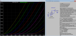
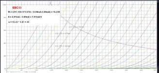
Here is EBC33 model, capacitance probably needs adjustment:
Thanks koonw, sorry to reply to late 🙂
Attachments
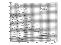
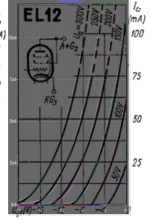
http://tdsl.duncanamps.com/sheets/el12/el12_2g.gif, noted that no screen current found.
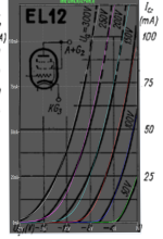
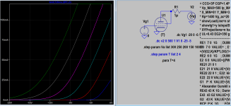
Here I want to release the triode model of EL12, then proceed to pentode model based on this triode model (some deviations from original):
Here I want to release the triode model of EL12, then proceed to pentode model based on this triode model (some deviations from original):
Code:
**** EL12T ** Advanced Grid Current **********************************
* Created on 03/23/2023 20:13 using paint_kit.jar 3.1
* www.dmitrynizh.com/tubeparams_image.htm
* Plate Curves image file: EL12T.png
* Data source link:
*----------------------------------------------------------------------------------
.SUBCKT EL12T 1 2 3 ; Plate Grid Cathode
+ PARAMS: CCG=3P  CGP=1.4P CCP=1.9P
+ MU=20.08 KG1=233.74 KP=125.23 KVB=1986.11 VCT=1.992E-4 EX=1.212
+ VGOFF=-0.6 IGA=0.001 IGB=0.3 IGC=8 IGEX=2
* Vp_MAX=480 Ip_MAX=160 Vg_step=5 Vg_start=0 Vg_count=11
* Rp=4000 Vg_ac=55 P_max=18 Vg_qui=-48 Vp_qui=300
* X_MIN=75 Y_MIN=19 X_SIZE=777 Y_SIZE=522 FSZ_X=1296 FSZ_Y=736 XYGrid=false
* showLoadLine=n showIp=y isDHT=n isPP=n isAsymPP=n showDissipLimit=y
* showIg1=y gridLevel2=y isInputSnapped=n
* XYProjections=n harmonicPlot=n dissipPlot=n
*----------------------------------------------------------------------------------
E1 7 0 VALUE={V(1,3)/KP*LOG(1+EXP(KP*(1/MU+(VCT+V(2,3))/SQRT(KVB+V(1,3)*V(1,3)))))}
RE1 7 0 1G  ; TO AVOID FLOATING NODES
G1 1 3 VALUE={(PWR(V(7),EX)+PWRS(V(7),EX))/KG1}
RCP 1 3 1G   ; TO AVOID FLOATING NODES
C1 2 3 {CCG} ; CATHODE-GRID
C2 2 1 {CGP} ; GRID=PLATE
C3 1 3 {CCP} ; CATHODE-PLATE
RE2 2 0 1G
EGC 8 0 VALUE={V(2,3)-VGOFF} ; POSITIVE GRID THRESHOLD
GG 2 3 VALUE={(IGA+IGB/(IGC+V(1,3)))*(MU/KG1)*(PWR(V(8),IGEX)+PWRS(V(8),IGEX))}
.ENDS
*$
Attachments
Last edited:
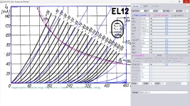
Here is EL12 pentode model, Vg2=350V:
Code:
**** EL12P ******************************************
* Created on 03/23/2023 23:18 using paint_kip.jar
* www.dmitrynizh.com/tubeparams_image.htm
* Plate Curves image file: EL12P.png
* Data source link: <plate curves URL>
*----------------------------------------------------------------------------------
.SUBCKT EL12P P G2 G K ; LTSpice tetrode.asy pinout
* .SUBCKT EL12P P G K G2 ; Koren Pentode Pspice pinout
+ PARAMS: MU=20.81 KG1=334.55 KP=114.63 KVB=1749.81 VCT=0.01371 EX=1.212 KG2=413.53 KNEE=4.681 KVC=1.594
+ KLAM=4.2E-8 KLAMG=2.745E-5 KNEE2=68.52 KNEX=4634.62  KNK=1.953E-4 KNG=1.953E-4 KNPL=0.1562 KNSL=3.563 KNPR=5.964 KNSR=18.63
+ CCG=3P CGP=1.4P CCP=1.9P VGOFF=-0.6 IGA=0.001 IGB=0.3 IGC=8 IGEX=2
* Vp_MAX=500 Ip_MAX=450 Vg_step=5 Vg_start=0 Vg_count=9
* X_MIN=81 Y_MIN=33 X_SIZE=700 Y_SIZE=630 FSZ_X=1296 FSZ_Y=736 XYGrid=false
* Rp=1400 Vg_ac=20 P_max=18 Vg_qui=-20 Vp_qui=300
* showLoadLine=n showIp=y isDHP=n isPP=n isAsymPP=n isUL=n showDissipLimit=y
* showIg1=y isInputSnapped=y addLocalNFB=n
* XYProjections=n harmonicPlot=y dissipPlot=n
* UL=0.43 EG2=350 gridLevel2=y addKink=y isTanhKnee=y advSigmoid=n
*----------------------------------------------------------------------------------
RE1  7 0  1G    ; DUMMY SO NODE 7 HAS 2 CONNECTIONS
E1   7 0  VALUE=  ; E1 BREAKS UP LONG EQUATION FOR G1.
+{V(G2,K)/KP*LOG(1+EXP((1/MU+(VCT+V(G,K))/SQRT(KVB+V(G2,K)*V(G2,K)))*KP))}
RE2  6 0  1G    ; DUMMY SO NODE 6 HAS 2 CONNECTIONS
E2  6 0  VALUE={(PWR(V(7),EX)+PWRS(V(7),EX))} ; Kg1 times KIT current
RE21 21 0 1
E21  21 0 VALUE={V(6)/KG1*ATAN((V(P,K)+KNEX)/KNEE)*TANH(V(P,K)/KNEE2)} ; Ip with knee but no slope and no kink
RE22 22 0 1 ; E22: kink curr deviation for plate
E22  22 0 VALUE={V(21)*LIMIT(KNK-V(G,K)*KNG,0,0.3)*(-ATAN((V(P,K)-KNPL)/KNSL)+ATAN((V(P,K)-KNPR)/KNSR))}
G1   P  K  VALUE={V(21)*(1+KLAMG*V(P,K))+KLAM*V(P,K) + V(22)}
* Alexander Gurskii screen current, see audioXpress 2/2011, with slope and kink added
RE43 43 K 1G ; Dummy
E43  43 G2 VALUE={0} ; Dummy
G2   43 K  VALUE={V(6)/KG2*(KVC-ATAN((V(P,K)+KNEX)/KNEE)*TANH(V(P,K)/KNEE2))/(1+KLAMG*V(P,K))-V(22)}
RCP  P K  1G     ; FOR CONVERGENCE
C1   K G  {CCG}  ; CATHODE-GRID 1
C2   G P  {CGP}  ; GRID 1-PLATE
C3   K P  {CCP}  ; CATHODE-PLATE
RE23 G 0 1G
GG G K VALUE={(IGA+IGB/(IGC+V(P,K)))*(MU/KG1)*
+(PWR(V(G,K)-VGOFF,IGEX)+PWRS(V(G,K)-VGOFF,IGEX))}
.ENDS
*$
Attachments
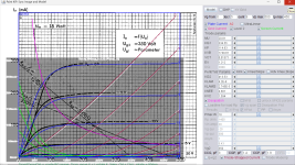

Here is EL12-250V model:
Code:
**** EL12P ******************************************
* Created on 03/23/2023 23:47 using paint_kip.jar
* www.dmitrynizh.com/tubeparams_image.htm
* Plate Curves image file: EL12P.png
* Data source link: <plate curves URL>
*----------------------------------------------------------------------------------
.SUBCKT EL12P P G2 G K ; LTSpice tetrode.asy pinout
* .SUBCKT EL12P P G K G2 ; Koren Pentode Pspice pinout
+ PARAMS: MU=20.81 KG1=327.69 KP=110.04 KVB=1749.81 VCT=0.01371 EX=1.212 KG2=413.53 KNEE=38.95 KVC=1.578
+ KLAM=4.2E-8 KLAMG=2.369E-4 KNEE2=11.36 KNEX=81.47  KNK=0.0125 KNG=0.0255 KNPL=0.1562 KNSL=3.563 KNPR=5.964 KNSR=18.63
+ CCG=3P CGP=1.4P CCP=1.9P VGOFF=-0.6 IGA=0.001 IGB=0.3 IGC=7.44 IGEX=2.14
* Vp_MAX=500 Ip_MAX=200 Vg_step=5 Vg_start=0 Vg_count=9
* X_MIN=51 Y_MIN=93 X_SIZE=711 Y_SIZE=577 FSZ_X=1296 FSZ_Y=736 XYGrid=true
* Rp=1400 Vg_ac=20 P_max=18 Vg_qui=-20 Vp_qui=300
* showLoadLine=n showIp=y isDHP=n isPP=n isAsymPP=n isUL=n showDissipLimit=y
* showIg1=y isInputSnapped=y addLocalNFB=n
* XYProjections=n harmonicPlot=y dissipPlot=n
* UL=0.43 EG2=250 gridLevel2=y addKink=y isTanhKnee=y advSigmoid=n
*----------------------------------------------------------------------------------
RE1  7 0  1G    ; DUMMY SO NODE 7 HAS 2 CONNECTIONS
E1   7 0  VALUE=  ; E1 BREAKS UP LONG EQUATION FOR G1.
+{V(G2,K)/KP*LOG(1+EXP((1/MU+(VCT+V(G,K))/SQRT(KVB+V(G2,K)*V(G2,K)))*KP))}
RE2  6 0  1G    ; DUMMY SO NODE 6 HAS 2 CONNECTIONS
E2  6 0  VALUE={(PWR(V(7),EX)+PWRS(V(7),EX))} ; Kg1 times KIT current
RE21 21 0 1
E21  21 0 VALUE={V(6)/KG1*ATAN((V(P,K)+KNEX)/KNEE)*TANH(V(P,K)/KNEE2)} ; Ip with knee but no slope and no kink
RE22 22 0 1 ; E22: kink curr deviation for plate
E22  22 0 VALUE={V(21)*LIMIT(KNK-V(G,K)*KNG,0,0.3)*(-ATAN((V(P,K)-KNPL)/KNSL)+ATAN((V(P,K)-KNPR)/KNSR))}
G1   P  K  VALUE={V(21)*(1+KLAMG*V(P,K))+KLAM*V(P,K) + V(22)}
* Alexander Gurskii screen current, see audioXpress 2/2011, with slope and kink added
RE43 43 K 1G ; Dummy
E43  43 G2 VALUE={0} ; Dummy
G2   43 K  VALUE={V(6)/KG2*(KVC-ATAN((V(P,K)+KNEX)/KNEE)*TANH(V(P,K)/KNEE2))/(1+KLAMG*V(P,K))-V(22)}
RCP  P K  1G     ; FOR CONVERGENCE
C1   K G  {CCG}  ; CATHODE-GRID 1
C2   G P  {CGP}  ; GRID 1-PLATE
C3   K P  {CCP}  ; CATHODE-PLATE
RE23 G 0 1G
GG G K VALUE={(IGA+IGB/(IGC+V(P,K)))*(MU/KG1)*
+(PWR(V(G,K)-VGOFF,IGEX)+PWRS(V(G,K)-VGOFF,IGEX))}
.ENDS
*$
Attachments
Last edited:
- Home
- Amplifiers
- Tubes / Valves
- Vacuum Tube SPICE Models