Hi Ripcord
The corresponding mu of the screen grid g2 is about 30 for the EL34. That means that g2 hides quite good the potentials of all electrodes behind.
So it will not make a big difference if g3 is connected to cathode or plate. I expect less than 5% of difference in cathode current.
Hence, you can also use every EL34 tetrode model which correctly models the currents for any screen voltage (mine behaves so), and just connect the screen to the plate to simulate triode mode.
cheers, Adrian
Adrian,
In your opinion, do the Ayumi tetrode models satisfy this requirement? I've always been a little leery of using tetrode models for what is actually a triode connected stage.
In your opinion, do the Ayumi tetrode models satisfy this requirement? I've always been a little leery of using tetrode models for what is actually a triode connected stage.
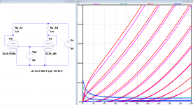
Shouldn't that give the same curves, but just in the reverse order? Both sets of parameters sweep the grid voltage between 0 and -30 volts, in 3 volt increments.
Yes it's the same, but I see it's pentode not UL curve when first one, maybe my eyes tired. What is wrong, are u not seeing a UL curve?
The parameters in my circuit are correct.Wrong params, should be
.dc V1 0 400 1 V2 0 -30 -3
There is a question about the displacement of the screen grid and, in general, the accuracy of the model of pentodes and tetrodes for UL inclusion. I've tried a lot of models already; all of these curves are more like pentodes. And then there are models of pentodes in triode switching, apparently not in vain they are made as separate models. The simple connection of the screen mesh to the anode in the pentode model obviously does not work correctly either.
Here are the correct curves for UL.
http://www.normankoren.com/Audio/Pent_UL_platecurve.gif
http://www.normankoren.com/Audio/Pent_P.gif
Improved vacuum tube models for SPICE, Part 1
Last edited:
I have done some models like that but wasn't sure what the IN+ is. You can use Paint Tool kit and paste the KT150 model into it then select "UL" see what UL curve is like. There is a UL trace curve in this forum, if you need it.
Attachments
Can you provide a link to this information? Where did you download these graphs and formulas.
https://www.diyaudio.com/forums/tubes-valves/243950-vacuum-tube-spice-models-258.html#post6338980
https://www.diyaudio.com/forums/tubes-valves/243950-vacuum-tube-spice-models-258.html#post6335499
KT150 curves by Sofia
I also have posted a number of output stage using E voltage dependent source to sim all 3 mods.
https://www.diyaudio.com/forums/tubes-valves/243950-vacuum-tube-spice-models-258.html#post6335499
KT150 curves by Sofia
I also have posted a number of output stage using E voltage dependent source to sim all 3 mods.
Attachments
It looks like it still does not work correctly and is especially noticeable with QQ03-12
Attachments
Last edited:
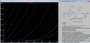
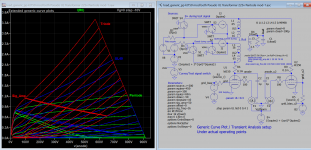
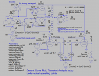
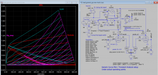
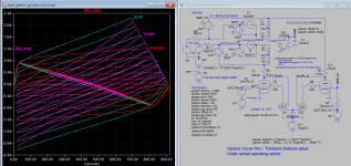
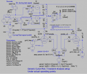
I have remodeled it now, all 3 modes as shown, please follow the notes for correct settings. For Pentode UL curves, the screen is set to Nominal voltage, in actual operation they're at HT potential, so the curves are extended from nominal curves.
*1 Nominal Vg2 means screen voltage in original Pentode curve
*2 If UL=1 triode mode, set nominal Vg2=0 as screen is now connected to plate, otherwise set to nominal voltage
I hope I have clear the air somewhat, any comment is fine.
*1 Nominal Vg2 means screen voltage in original Pentode curve
*2 If UL=1 triode mode, set nominal Vg2=0 as screen is now connected to plate, otherwise set to nominal voltage
I hope I have clear the air somewhat, any comment is fine.
Attachments
Last edited:
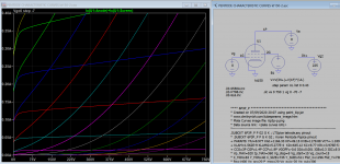
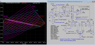
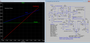
Here are some extended curve plots under actual operating conditions. You can plot composite tube curves, loadline etc quite completed by is workable.
Attachments
Last edited:
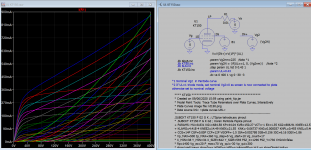
I think there is a mistake for Triode mode plot, the screen supply should be set to 0 instead of HT. Here is the correct model.
Attachments
Last edited:
- Home
- Amplifiers
- Tubes / Valves
- Vacuum Tube SPICE Models