Does anyone have a model for 12A4?
Code:
.subckt 12A4  P G K
    Bp  P K  I=(0.04842259598m)*uramp(V(P,K)*ln(1.0+(-0.1171696503)+exp((6.561427624)+(6.561427624)*((18.54552963)+(-100.6055605m)*V(G,K))*V(G,K)/sqrt((40.8808477)**2+(V(P,K)-(25.43292096))**2)))/(6.561427624))**(1.491616235)
.ends
https://www.google.com/url?sa=t&rct...riode_nh.txt&usg=AOvVaw0RyCFmH6i8Mcq4dprcUZAH
Last edited:
Hi, I'm looking for a model for RES964
Thanks
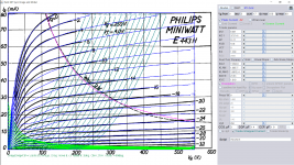
Don't find sufficient data for RES964, use close substitute E443H instead.
Code:
**** E443H ******************************************
* Created on 11/13/2018 23:18 using paint_kip.jar
* [url]www.dmitrynizh.com/tubeparams_image.htm[/url]
* Plate Curves image file: e443h.png
* Data source link: <plate curves URL>
*----------------------------------------------------------------------------------
.SUBCKT E443H P G2 G K ; LTSpice tetrode.asy pinout
* .SUBCKT E443H P G K G2 ; Koren Pentode Pspice pinout
+ PARAMS: MU=8.001 KG1=3737.41 KP=51.11 KVB=10.8 VCT=0 EX=1.338 KG2=11692.8 KNEE=23.63 KVC=1.619
+ KLAM=1.08E-7 KLAMG=3.587E-4   KNK=-0.044 KNG=0.006 KNPL=50 KNSL=11 KNPR=120 KNSR=29
+ CCG=3P CGP=1.4P CCP=1.9P RGI=2000.0
* Vp_MAX=550 Ip_MAX=80 Vg_step=2 Vg_start=0 Vg_count=17
* X_MIN=41 Y_MIN=45 X_SIZE=976 Y_SIZE=716 FSZ_X=1550 FSZ_Y=878 XYGrid=false
* Rp=1400 Vg_ac=20 P_max=9 Vg_qui=-16 Vp_qui=300
* showLoadLine=n showIp=y isDHP=n isPP=n isAsymPP=n isUL=n showDissipLimit=y
* showIg1=n isInputSnapped=y addLocalNFB=n
* XYProjections=n harmonicPlot=y dissipPlot=n
* UL=0.43 EG2=250 gridLevel2=n addKink=y isTanhKnee=n advSigmoid=n
*----------------------------------------------------------------------------------
RE1  7 0  1G    ; DUMMY SO NODE 7 HAS 2 CONNECTIONS
E1   7 0  VALUE=  ; E1 BREAKS UP LONG EQUATION FOR G1.
+{V(G2,K)/KP*LOG(1+EXP((1/MU+(VCT+V(G,K))/SQRT(KVB+V(G2,K)*V(G2,K)))*KP))}
RE2  6 0  1G    ; DUMMY SO NODE 6 HAS 2 CONNECTIONS
E2  6 0  VALUE={(PWR(V(7),EX)+PWRS(V(7),EX))} ; Kg1 times KIT current
RE21 21 0 1
E21  21 0 VALUE={V(6)/KG1*ATAN(V(P,K)/KNEE)} ; Ip with knee but no slope and no kink
RE22 22 0 1 ; E22: kink curr deviation for plate
E22  22 0 VALUE={V(21)*LIMIT(KNK-V(G,K)*KNG,0,0.3)*(-ATAN((V(P,K)-KNPL)/KNSL)+ATAN((V(P,K)-KNPR)/KNSR))}
G1   P  K  VALUE={V(21)*(1+KLAMG*V(P,K))+KLAM*V(P,K) + V(22)}
* Alexander Gurskii screen current, see audioXpress 2/2011, with slope and kink added
RE43 43 K 1G ; Dummy
E43  43 G2 VALUE={0} ; Dummy
G2   43 K  VALUE={V(6)/KG2*(KVC-ATAN(V(P,K)/KNEE))/(1+KLAMG*V(P,K))-V(22)}
RCP  P K  1G     ; FOR CONVERGENCE
C1   K G  {CCG}  ; CATHODE-GRID 1
C2   G P  {CGP}  ; GRID 1-PLATE
C3   K P  {CCP}  ; CATHODE-PLATE
R1   G 5  {RGI}  ; FOR GRID CURRENT
D3   5 K  DX     ; FOR GRID CURRENT }
.MODEL DX D(IS=1N RS=1 CJO=10PF TT=1N)
.ENDS
*$


* The following triode model is derived from pentode model, see above.
* In the triode model, all spice parameters come directly from the pentode model, except for Kg1,
* which for triode-strapped pentodes is derived from pentode's Kg1, Kg2 and Kvc as
*
*    4Kg1Kg2 / ((2Kvc-Pi)(2Kg1+PiKg2))

**** E443H ******************************************
* Created on 11/13/2018 23:18 using paint_kit.jar 4.7
* [url]www.dmitrynizh.com/tubeparams_image.htm[/url]
* Plate Curves image file: e443h.png
* Data source link: <plate curves URL>
*----------------------------------------------------------------------------------
.SUBCKT TRIODE_E443H 1 2 3 ; Plate Grid Cathode
+ PARAMS: CCG=3P  CGP=1.4P CCP=1.9P RGI=2000
+ MU=8.001 KG1=41016.82 KP=51.11 KVB=10.8 VCT=0 EX=1.338
* Vp_MAX=550 Ip_MAX=80 Vg_step=2 Vg_start=0 Vg_count=17
* Rp=1400 Vg_ac=20 P_max=9 Vg_qui=-16 Vp_qui=300
* X_MIN=41 Y_MIN=45 X_SIZE=976 Y_SIZE=716 FSZ_X=1550 FSZ_Y=878 XYGrid=false
* showLoadLine=n showIp=y isDHT=n isPP=n isAsymPP=n showDissipLimit=y
* showIg1=n gridLevel2=n isInputSnapped=y
* XYProjections=n harmonicPlot=y dissipPlot=n
*----------------------------------------------------------------------------------
E1 7 0 VALUE={V(1,3)/KP*LOG(1+EXP(KP*(1/MU+(VCT+V(2,3))/SQRT(KVB+V(1,3)*V(1,3)))))}
RE1 7 0 1G  ; TO AVOID FLOATING NODES
G1 1 3 VALUE={(PWR(V(7),EX)+PWRS(V(7),EX))/KG1}
RCP 1 3 1G   ; TO AVOID FLOATING NODES
C1 2 3 {CCG} ; CATHODE-GRID
C2 2 1 {CGP} ; GRID=PLATE
C3 1 3 {CCP} ; CATHODE-PLATE
D3 5 3 DX ; POSITIVE GRID CURRENT
R1 2 5 {RGI} ; POSITIVE GRID CURRENT
.MODEL DX D(IS=1N RS=1 CJO=10PF TT=1N)
.ENDS
*$
Attachments
Hi everyone
I am looking for a model of Electro Harmonix 6922.
It is said out there that the 6N23P is the same, but the only model available is inaccurate, its iv curves are more like Siemens E88CC/6922.
Thanks in advance.
I am looking for a model of Electro Harmonix 6922.
It is said out there that the 6N23P is the same, but the only model available is inaccurate, its iv curves are more like Siemens E88CC/6922.
Thanks in advance.
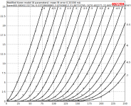
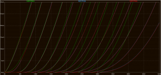
I made model from a set of curves that are supposedly for a 6922EH that compare to a set for for a 6N23P that I have. Who knows...
I made a comparison in LTspice in the image below.
U1 = Philips E88CC
U2 = Supposed 6922EH
U3 = 6N23P from Soviet data sheet.
I made a comparison in LTspice in the image below.
U1 = Philips E88CC
U2 = Supposed 6922EH
U3 = 6N23P from Soviet data sheet.
Code:
* 6922EH LTSpice model
* Modified Koren model (8 parameters) mean fit error 0.20198mA
* Traced by Wayne Clay on 05/29/2016 using Curve Captor v0.9.1
* and Engauge Digitizer
.subckt 6922EH  P G K
    Bp  P K  I=
+ (0.08061132734m)*uramp(V(P,K)*ln(1.0+(-0.03708608981)+exp((3.87608812)+
+ (3.87608812)*((31.88733765)+(-1070.482271m)*V(G,K))*V(G,K)/sqrt((22.6657093)**2+
+ (V(P,K)-(4.717434742))**2)))/(3.87608812))**(1.322643185)
    Cgp G P 2.2p ; 0.7p added (1.5p)
    Cgk G K 4.2p ; 0.7p added (3.5p)
    Cpk P K 2.2p ; 0.2p added (2.0p)
    Rpk P K 1G ; to avoid floating nodes
    d3  G K dx1
.model dx1 d(is=1n rs=2k cjo=1pf N=1.5 tt=1n)
.ends 6922EH
Code:
* ==============================================================
* 6N23P LTSpice model
* Modified Koren model (8 parameters): mean fit error 0.182649mA
* Traced by Wayne Clay on 08/22/2018 using Curve Captor v0.9.1
* and Engauge Digitizer from Soviet data sheet
* ==============================================================
.subckt 6N23P  P G K
    Bp  P K  I=
+ (0.09199263401m)*uramp(V(P,K)*ln(1.0+(-0.04545642112)+exp((4.06290859)+
+ (4.06290859)*((30.26769611)+(-1093.389027m)*V(G,K))*V(G,K)/sqrt((29.02430003)**2+
+ (V(P,K)-(11.49369847))**2)))/(4.06290859))**(1.290098711)
    Cgp G P 2.3p ; 0.7p added (1.6p)
    Cgk G K 4.3p ; 0.7p added (3.6p)
    Cpk P K 2.3p ; 0.2p added (2.1p)
    Rpk P K 1.0G ; to avoid floating nodes in mu-follower
    d3  G K dx1
.model dx1 d(is=1n rs=2k cjo=1pf N=1.5 tt=1n)
.ends 6N23P
Attachments

I made model from a set of curves that are supposedly for a 6922EH that compare to a set for for a 6N23P that I have.
I compared the actual 6N23p with supposed 6922eh you attached, is it close, esp. towards the end. But I still think 6922eh plot is derived from the original 6N23p curve which looks so much alike but actually has much differences. Electroharmonix provides 6922eh datasheet with data only no curve plots at all (that I can find). So one must plot the 6922eh curve to see the real differences!!
Attachments
Last edited:
Both models are very close, maybe the 6922EH is based on the 6N23P or is the same valve.
The 6N23P model from post#1833 is far better than the one available on Russian forums.
The 6N23P model from post#1833 is far better than the one available on Russian forums.
6AR6 SPICE Models
The pentode model isn't that accurate at high -Vg voltages, use it at your risk... 😉
Triode-Connected:
Pentode:
The pentode model isn't that accurate at high -Vg voltages, use it at your risk... 😉
Triode-Connected:
Code:
*
* Generic triode model: 6AR6_T_AN
* Copyright 2003--2008 by Ayumi Nakabayashi, All rights reserved.
* Version 3.10, Generated on Wed Nov 21 10:09:07 2018
*                 Anode
*                 | Grid
*                 | | Cathode
*                 | | |
.SUBCKT 6AR6_T_AN A G K
BGG   GG   0 V=V(G,K)+0.99999983
BM1   M1   0 V=(0.07705486*(URAMP(V(A,K))+1e-10))**-0.83978416
BM2   M2   0 V=(0.64108477*(URAMP(V(GG)+URAMP(V(A,K))/4.6579181)+1e-10))**2.3397842
BP    P    0 V=0.0012435333*(URAMP(V(GG)+URAMP(V(A,K))/7.265682)+1e-10)**1.5
BIK   IK   0 V=U(V(GG))*V(P)+(1-U(V(GG)))*0.00076400462*V(M1)*V(M2)
BIG   IG   0 V=0.00062176665*URAMP(V(G,K))**1.5*(URAMP(V(G,K))/(URAMP(V(A,K))+URAMP(V(G,K)))*1.2+0.4)
BIAK  A    K I=URAMP(V(IK,IG)-URAMP(V(IK,IG)-(0.00088713481*URAMP(V(A,K))**1.5)))+1e-10*V(A,K)
BIGK  G    K I=V(IG)
* CAPS
CGA   G    A 0.55p
CGK   G    K 11p
CAK   A    K 7p
.ENDS
Pentode:
Code:
*
* Generic pentode model: 6AR6_AN
* Copyright 2003--2008 by Ayumi Nakabayashi, All rights reserved.
* Version 3.10, Generated on Wed Nov 21 10:08:46 2018
*               Anode
*               | Screen Grid
*               | |  Control Grid
*               | |  |  Cathode
*               | |  |  |
.SUBCKT 6AR6_AN A G2 G1 K
BGG   GG   0 V=V(G1,K)+0.99999983
BM1   M1   0 V=(0.07705486*(URAMP(V(G2,K))+1e-10))**-0.83978416
BM2   M2   0 V=(0.64108477*(URAMP(V(GG)+URAMP(V(G2,K))/4.6579181)))**2.3397842
BP    P    0 V=0.0012435333*(URAMP(V(GG)+URAMP(V(G2,K))/7.265682))**1.5
BIK   IK   0 V=U(V(GG))*V(P)+(1-U(V(GG)))*0.00076400462*V(M1)*V(M2)
BIG   IG   0 V=0.00062176665*URAMP(V(G1,K))**1.5*(URAMP(V(G1,K))/(URAMP(V(A,K))+URAMP(V(G1,K)))*1.2+0.4)
BIK2  IK2  0 V=V(IK,IG)*(1-0.4*(EXP(-URAMP(V(A,K))/URAMP(V(G2,K))*15)-EXP(-15)))
BIG2T IG2T 0 V=V(IK2)*(0.946161216*(1-URAMP(V(A,K))/(URAMP(V(A,K))+10))**1.5+0.053838784)
BIK3  IK3  0 V=V(IK2)*(URAMP(V(A,K))+6680)/(URAMP(V(G2,K))+6680)
BIK4  IK4  0 V=V(IK3)-URAMP(V(IK3)-(0.00088713481*(URAMP(V(A,K))+URAMP(URAMP(V(G2,K))-URAMP(V(A,K))))**1.5))
BIP   IP   0 V=URAMP(V(IK4,IG2T)-URAMP(V(IK4,IG2T)-(0.00088713481*URAMP(V(A,K))**1.5)))
BIAK  A    K I=V(IP)+1e-10*V(A,K)
BIG2  G2   K I=URAMP(V(IK4,IP))
BIGK  G1   K I=V(IG)
* CAPS
CGA   G1  A  0.55p
CGK   G1  K  6.6p
C12   G1  G2 4.4p
CAK   A   K  7p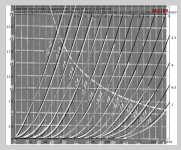
.ENDSA very difficult curve to paint.
Code:
**** 6384P ******************************************
* Created on 11/21/2018 16:59 using paint_kip.jar
* [url=http://www.dmitrynizh.com/tubeparams_image.htm]Model Paint Tools: Trace Tube Parameters over Plate Curves, Interactively[/url]
* Plate Curves image file: 6384p.png
* Data source link: <plate curves URL>
*----------------------------------------------------------------------------------
.SUBCKT 6384P P G2 G K ; LTSpice tetrode.asy pinout
* .SUBCKT 6384P P G K G2 ; Koren Pentode Pspice pinout
+ PARAMS: MU=6.42 KG1=1695.76 KP=43.17 KVB=12 VCT=0 EX=1.386 KG2=2541 KNEE=59.04 KVC=1.571
+ KLAM=1.44E-5 KLAMG=1.359E-6 KNEE2=20 KNEX=30  KNK=-0.044 KNG=0.006
+ CCG=3P CGP=1.4P CCP=1.9P RGI=2000.0
* Vp_MAX=800 Ip_MAX=400 Vg_step=10 Vg_start=0 Vg_count=11
* X_MIN=108 Y_MIN=74 X_SIZE=966 Y_SIZE=715 FSZ_X=1550 FSZ_Y=878 XYGrid=false
* Rp=1400 Vg_ac=20 P_max=30 Vg_qui=-50 Vp_qui=300
* showLoadLine=n showIp=y isDHP=n isPP=n isAsymPP=n isUL=n showDissipLimit=y
* showIg1=n isInputSnapped=y addLocalNFB=n
* XYProjections=n harmonicPlot=y dissipPlot=n
* UL=0.43 EG2=325 gridLevel2=n addKink=n isTanhKnee=y advSigmoid=n
*----------------------------------------------------------------------------------
RE1  7 0  1G    ; DUMMY SO NODE 7 HAS 2 CONNECTIONS
E1   7 0  VALUE=  ; E1 BREAKS UP LONG EQUATION FOR G1.
+{V(G2,K)/KP*LOG(1+EXP((1/MU+(VCT+V(G,K))/SQRT(KVB+V(G2,K)*V(G2,K)))*KP))}
RE2  6 0  1G    ; DUMMY SO NODE 6 HAS 2 CONNECTIONS
E2  6 0  VALUE={(PWR(V(7),EX)+PWRS(V(7),EX))} ; Kg1 times KIT current
G1   P K  VALUE={V(6)/KG1*ATAN((V(P,K)+KNEX)/KNEE)*TANH(V(P,K)/KNEE2)*(1+KLAMG*V(P,K))+KLAM*V(P,K)}
* Alexander Gurskii screen current, see audioXpress 2/2011
RE4K 4K K 1G ; Dummy, per Alex request
E4K 4K  4 VALUE={0} ; Dummy, per Alex request
G4K 4K K VALUE={V(6)/KG2*(KVC-ATAN((V(P,K)+KNEX)/KNEE)*TANH(V(P,K)/KNEE2))/(1+KLAMG*V(P,K))}
RCP  P K  1G     ; FOR CONVERGENCE
C1   K G  {CCG}  ; CATHODE-GRID 1
C2   G P  {CGP}  ; GRID 1-PLATE
C3   K P  {CCP}  ; CATHODE-PLATE
R1   G 5  {RGI}  ; FOR GRID CURRENT
D3   5 K  DX     ; FOR GRID CURRENT }
.MODEL DX D(IS=1N RS=1 CJO=10PF TT=1N)
.ENDS
*$


* The following triode model is derived from pentode model, see above.
* In the triode model, all spice parameters come directly from the pentode model, except for Kg1,
* which for triode-strapped pentodes is derived from pentode's Kg1, Kg2 and Kvc as
*
*    4Kg1Kg2 / ((2Kvc-Pi)(2Kg1+PiKg2))

**** 6384P ******************************************
* Created on 11/21/2018 16:59 using paint_kit.jar 4.7
* [url=http://www.dmitrynizh.com/tubeparams_image.htm]Model Paint Tools: Trace Tube Parameters over Plate Curves, Interactively[/url]
* Plate Curves image file: 6384p.png
* Data source link: <plate curves URL>
*----------------------------------------------------------------------------------
.SUBCKT TRIODE_6384P 1 2 3 ; Plate Grid Cathode
+ PARAMS: CCG=3P  CGP=1.4P CCP=1.9P RGI=2000
+ MU=6.42 KG1=∞ KP=43.17 KVB=12 VCT=0 EX=1.386
* Vp_MAX=800 Ip_MAX=400 Vg_step=10 Vg_start=0 Vg_count=11
* Rp=1400 Vg_ac=20 P_max=30 Vg_qui=-50 Vp_qui=300
* X_MIN=108 Y_MIN=74 X_SIZE=966 Y_SIZE=715 FSZ_X=1550 FSZ_Y=878 XYGrid=false
* showLoadLine=n showIp=y isDHT=n isPP=n isAsymPP=n showDissipLimit=y
* showIg1=n gridLevel2=n isInputSnapped=y
* XYProjections=n harmonicPlot=y dissipPlot=n
*----------------------------------------------------------------------------------
E1 7 0 VALUE={V(1,3)/KP*LOG(1+EXP(KP*(1/MU+(VCT+V(2,3))/SQRT(KVB+V(1,3)*V(1,3)))))}
RE1 7 0 1G  ; TO AVOID FLOATING NODES
G1 1 3 VALUE={(PWR(V(7),EX)+PWRS(V(7),EX))/KG1}
RCP 1 3 1G   ; TO AVOID FLOATING NODES
C1 2 3 {CCG} ; CATHODE-GRID
C2 2 1 {CGP} ; GRID=PLATE
C3 1 3 {CCP} ; CATHODE-PLATE
D3 5 3 DX ; POSITIVE GRID CURRENT
R1 2 5 {RGI} ; POSITIVE GRID CURRENT
.MODEL DX D(IS=1N RS=1 CJO=10PF TT=1N)
.ENDS
*$
Attachments
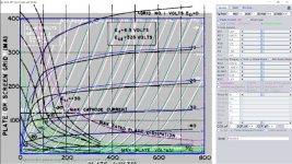
This one with G2 current and no kink.
Code:
**** 6384P ******************************************
* Created on 11/21/2018 19:44 using paint_kip.jar
* [url=http://www.dmitrynizh.com/tubeparams_image.htm]Model Paint Tools: Trace Tube Parameters over Plate Curves, Interactively[/url]
* Plate Curves image file: 6384p.png
* Data source link: <plate curves URL>
*----------------------------------------------------------------------------------
.SUBCKT 6384P P G2 G K ; LTSpice tetrode.asy pinout
* .SUBCKT 6384P P G K G2 ; Koren Pentode Pspice pinout
+ PARAMS: MU=6.289 KG1=10060.6 KP=34.13 KVB=12.6 VCT=6.44 EX=1.774 KG2=20295.48 KNEE=1.877 KVC=1.697
+ KLAM=4.922E-11 KLAMG=1.728E-7  KD=0.44 KC=0.14 KR1=0.0013 KR2=0.064 KVBG=0.015 KNK=-0.044 KNG=0.006
+ CCG=3P CGP=1.4P CCP=1.9P RGI=2000.0
* Vp_MAX=800 Ip_MAX=400 Vg_step=10 Vg_start=0 Vg_count=11
* X_MIN=108 Y_MIN=74 X_SIZE=966 Y_SIZE=715 FSZ_X=1550 FSZ_Y=878 XYGrid=false
* Rp=1400 Vg_ac=20 P_max=30 Vg_qui=-50 Vp_qui=300
* showLoadLine=n showIp=y isDHP=n isPP=n isAsymPP=n isUL=n showDissipLimit=y
* showIg1=n isInputSnapped=y addLocalNFB=n
* XYProjections=n harmonicPlot=y dissipPlot=n
* UL=0.43 EG2=325 gridLevel2=n addKink=n isTanhKnee=n advSigmoid=y
*----------------------------------------------------------------------------------
RE1  7 0  1G    ; DUMMY SO NODE 7 HAS 2 CONNECTIONS
E1   7 0  VALUE=  ; E1 BREAKS UP LONG EQUATION FOR G1.
+{V(G2,K)/KP*LOG(1+EXP((1/MU+(VCT+V(G,K))/SQRT(KVB+V(G2,K)*V(G2,K)))*KP))}
RE2  6 0  1G    ; DUMMY SO NODE 6 HAS 2 CONNECTIONS
E2  6 0  VALUE={(PWR(V(7),EX)+PWRS(V(7),EX))} ; Kg1 times KIT current
E4   8 0  VALUE={PWR(V(1,3)/KNEE/(V(6)*KVBG),2)}
E5   9 0  VALUE={SQRT(1-EXP(-V(8)*(KC+KR1*V(8))/(KD+KR2*V(8))))*1.5708}
RE4  8 0  1
RE5  9 0  1
G1   P K  VALUE={V(6)/KG1*V(9)*(1+KLAMG*V(P,K))+KLAM*V(P,K)}
G2   G2 K  VALUE={V(6)/KG2*(KVC-V(9))/(1+KLAMG*V(P,K))}
RCP  P K  1G     ; FOR CONVERGENCE
C1   K G  {CCG}  ; CATHODE-GRID 1
C2   G P  {CGP}  ; GRID 1-PLATE
C3   K P  {CCP}  ; CATHODE-PLATE
R1   G 5  {RGI}  ; FOR GRID CURRENT
D3   5 K  DX     ; FOR GRID CURRENT }
.MODEL DX D(IS=1N RS=1 CJO=10PF TT=1N)
.ENDS
*$


* The following triode model is derived from pentode model, see above.
* In the triode model, all spice parameters come directly from the pentode model, except for Kg1,
* which for triode-strapped pentodes is derived from pentode's Kg1, Kg2 and Kvc as
*
*    4Kg1Kg2 / ((2Kvc-Pi)(2Kg1+PiKg2))

**** 6384P ******************************************
* Created on 11/21/2018 19:44 using paint_kit.jar 4.7
* [url=http://www.dmitrynizh.com/tubeparams_image.htm]Model Paint Tools: Trace Tube Parameters over Plate Curves, Interactively[/url]
* Plate Curves image file: 6384p.png
* Data source link: <plate curves URL>
*----------------------------------------------------------------------------------
.SUBCKT TRIODE_6384P 1 2 3 ; Plate Grid Cathode
+ PARAMS: CCG=3P  CGP=1.4P CCP=1.9P RGI=2000
+ MU=6.289 KG1=38576.94 KP=34.13 KVB=12.6 VCT=6.44 EX=1.774
* Vp_MAX=800 Ip_MAX=400 Vg_step=10 Vg_start=0 Vg_count=11
* Rp=1400 Vg_ac=20 P_max=30 Vg_qui=-50 Vp_qui=300
* X_MIN=108 Y_MIN=74 X_SIZE=966 Y_SIZE=715 FSZ_X=1550 FSZ_Y=878 XYGrid=false
* showLoadLine=n showIp=y isDHT=n isPP=n isAsymPP=n showDissipLimit=y
* showIg1=n gridLevel2=n isInputSnapped=y
* XYProjections=n harmonicPlot=y dissipPlot=n
*----------------------------------------------------------------------------------
E1 7 0 VALUE={V(1,3)/KP*LOG(1+EXP(KP*(1/MU+(VCT+V(2,3))/SQRT(KVB+V(1,3)*V(1,3)))))}
RE1 7 0 1G  ; TO AVOID FLOATING NODES
G1 1 3 VALUE={(PWR(V(7),EX)+PWRS(V(7),EX))/KG1}
RCP 1 3 1G   ; TO AVOID FLOATING NODES
C1 2 3 {CCG} ; CATHODE-GRID
C2 2 1 {CGP} ; GRID=PLATE
C3 1 3 {CCP} ; CATHODE-PLATE
D3 5 3 DX ; POSITIVE GRID CURRENT
R1 2 5 {RGI} ; POSITIVE GRID CURRENT
.MODEL DX D(IS=1N RS=1 CJO=10PF TT=1N)
.ENDS
*$
Attachments
Thank you both very much Jazbo8 and Koonw. I'll have to give all the models posted a try. I figured those kinks would make finding an accurate pentode model damn near impossible; thankfully I intend to triode strap my 6AR6s...
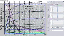
This one goes up to +30V A2: Because there are some updates for paint tools it takes awhile to understand all the features to use to paint more accurate model. In this one KVB is used to align plot above 0 (A2).
Code:
**** 6384P ******************************************
* Created on 11/21/2018 23:49 using paint_kip.jar
* [url=http://www.dmitrynizh.com/tubeparams_image.htm]Model Paint Tools: Trace Tube Parameters over Plate Curves, Interactively[/url]
* Plate Curves image file: 6384p.png
* Data source link: <plate curves URL>
*----------------------------------------------------------------------------------
.SUBCKT 6384P P G2 G K ; LTSpice tetrode.asy pinout
* .SUBCKT 6384P P G K G2 ; Koren Pentode Pspice pinout
+ PARAMS: MU=6.037 KG1=35240.65 KP=32.95 KVB=2276.55 VCT=9.94 EX=2 KG2=49180.17 KNEE=0.3187 KVC=1.571
+ KLAM=1.621E-6 KLAMG=3.046E-4  KD=0.44 KC=0.14 KR1=0.0013 KR2=0.064 KVBG=0.015 KNK=-0.044 KNG=0.006
+ CCG=3P CGP=1.4P CCP=1.9P RGI=2000.0
* Vp_MAX=800 Ip_MAX=400 Vg_step=10 Vg_start=30 Vg_count=14
* X_MIN=108 Y_MIN=78 X_SIZE=966 Y_SIZE=711 FSZ_X=1550 FSZ_Y=878 XYGrid=false
* Rp=1400 Vg_ac=20 P_max=30 Vg_qui=-35 Vp_qui=300
* showLoadLine=n showIp=y isDHP=n isPP=n isAsymPP=n isUL=n showDissipLimit=y
* showIg1=n isInputSnapped=y addLocalNFB=n
* XYProjections=n harmonicPlot=y dissipPlot=n
* UL=0.43 EG2=325 gridLevel2=n addKink=n isTanhKnee=n advSigmoid=y
*----------------------------------------------------------------------------------
RE1  7 0  1G    ; DUMMY SO NODE 7 HAS 2 CONNECTIONS
E1   7 0  VALUE=  ; E1 BREAKS UP LONG EQUATION FOR G1.
+{V(G2,K)/KP*LOG(1+EXP((1/MU+(VCT+V(G,K))/SQRT(KVB+V(G2,K)*V(G2,K)))*KP))}
RE2  6 0  1G    ; DUMMY SO NODE 6 HAS 2 CONNECTIONS
E2  6 0  VALUE={(PWR(V(7),EX)+PWRS(V(7),EX))} ; Kg1 times KIT current
E4   8 0  VALUE={PWR(V(1,3)/KNEE/(V(6)*KVBG),2)}
E5   9 0  VALUE={SQRT(1-EXP(-V(8)*(KC+KR1*V(8))/(KD+KR2*V(8))))*1.5708}
RE4  8 0  1
RE5  9 0  1
G1   P K  VALUE={V(6)/KG1*V(9)*(1+KLAMG*V(P,K))+KLAM*V(P,K)}
G2   G2 K  VALUE={V(6)/KG2*(KVC-V(9))/(1+KLAMG*V(P,K))}
RCP  P K  1G     ; FOR CONVERGENCE
C1   K G  {CCG}  ; CATHODE-GRID 1
C2   G P  {CGP}  ; GRID 1-PLATE
C3   K P  {CCP}  ; CATHODE-PLATE
R1   G 5  {RGI}  ; FOR GRID CURRENT
D3   5 K  DX     ; FOR GRID CURRENT }
.MODEL DX D(IS=1N RS=1 CJO=10PF TT=1N)
.ENDS
*$


* The following triode model is derived from pentode model, see above.
* In the triode model, all spice parameters come directly from the pentode model, except for Kg1,
* which for triode-strapped pentodes is derived from pentode's Kg1, Kg2 and Kvc as
*
*    4Kg1Kg2 / ((2Kvc-Pi)(2Kg1+PiKg2))

**** 6384P ******************************************
* Created on 11/21/2018 23:49 using paint_kit.jar 4.7
* [url=http://www.dmitrynizh.com/tubeparams_image.htm]Model Paint Tools: Trace Tube Parameters over Plate Curves, Interactively[/url]
* Plate Curves image file: 6384p.png
* Data source link: <plate curves URL>
*----------------------------------------------------------------------------------
.SUBCKT TRIODE_6384P 1 2 3 ; Plate Grid Cathode
+ PARAMS: CCG=3P  CGP=1.4P CCP=1.9P RGI=2000
+ MU=6.037 KG1=7.703E7 KP=32.95 KVB=2276.55 VCT=9.94 EX=2
* Vp_MAX=800 Ip_MAX=400 Vg_step=10 Vg_start=30 Vg_count=14
* Rp=1400 Vg_ac=20 P_max=30 Vg_qui=-35 Vp_qui=300
* X_MIN=108 Y_MIN=78 X_SIZE=966 Y_SIZE=711 FSZ_X=1550 FSZ_Y=878 XYGrid=false
* showLoadLine=n showIp=y isDHT=n isPP=n isAsymPP=n showDissipLimit=y
* showIg1=n gridLevel2=n isInputSnapped=y
* XYProjections=n harmonicPlot=y dissipPlot=n
*----------------------------------------------------------------------------------
E1 7 0 VALUE={V(1,3)/KP*LOG(1+EXP(KP*(1/MU+(VCT+V(2,3))/SQRT(KVB+V(1,3)*V(1,3)))))}
RE1 7 0 1G  ; TO AVOID FLOATING NODES
G1 1 3 VALUE={(PWR(V(7),EX)+PWRS(V(7),EX))/KG1}
RCP 1 3 1G   ; TO AVOID FLOATING NODES
C1 2 3 {CCG} ; CATHODE-GRID
C2 2 1 {CGP} ; GRID=PLATE
C3 1 3 {CCP} ; CATHODE-PLATE
D3 5 3 DX ; POSITIVE GRID CURRENT
R1 2 5 {RGI} ; POSITIVE GRID CURRENT
.MODEL DX D(IS=1N RS=1 CJO=10PF TT=1N)
.ENDS
*$
Attachments

Hi all,
good news for all who does signal conditioning with vacuum diodes: I just released a 5AL6 spice model fitted to a measured Tungsram sample, able to accurate consider the "Anlauf" current.
You may now simulate audion circuits, signal level detection circuits and this stuff.
download is here:
http://adrianimmler.simplesite.com/440951057
kind regards, Adrian
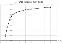
By the way, I just noticed that I spelled the vacuum diodes' name wrong in my post #1843.
I meant the 6AL5!!
I meant the 6AL5!!
Spice model needed
Hello to all my diy colleagues.
Can someone help me with the spice patterns for the following tubes:
- 6C33C-B (for both triodes)
- EF86 PHILIPS
- ECC83 PHILIPS
Thank you in advance
Hello to all my diy colleagues.
Can someone help me with the spice patterns for the following tubes:
- 6C33C-B (for both triodes)
- EF86 PHILIPS
- ECC83 PHILIPS
Thank you in advance
- Home
- Amplifiers
- Tubes / Valves
- Vacuum Tube SPICE Models