Hi everyone. I am looking for spice models supporting grid currentst reasonably. Tubes in question: EL34, KT77, well and ideally also GU50. My question refers to grids G2 and also G1.
G2 is obvious: modeling proper load of G2 unter high load/overdrive conditions.
G1: well, in the real world, the current on that grid and hence biasing of the tubes. Very noticeably - in one example simply changing the G1-resistor from 220k to 180 lead to a bias voltage which was completely off range. I would like to model that effect.
And in the case of GU50 and related tubes it would help to find appropriate grid leak resistors at all (there is some lack of documentation in the data sheets).
The 6e6p_e model which Koonw posted has many syntax errors:The 6E6P model returns the error message below. Is anyone aware of an alternate pentode mode version? Thanks.
- missing * signs for comment lines
- missing + signs for continuation lines
- mising multiplication * signs in formulas
Attachments
Hi BeaHi everyone. I am looking for spice models supporting grid currentst reasonably. Tubes in question: EL34, KT77, well and ideally also GU50. My question refers to grids G2 and also G1.
G2 is obvious: modeling proper load of G2 unter high load/overdrive conditions.
G1: well, in the real world, the current on that grid and hence biasing of the tubes. Very noticeably - in one example simply changing the G1-resistor from 220k to 180 lead to a bias voltage which was completely off range. I would like to model that effect.
And in the case of GU50 and related tubes it would help to find appropriate grid leak resistors at all (there is some lack of documentation in the data sheets).
I did a EL34 model some years ago, with the following approach:
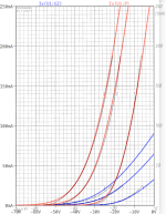
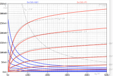
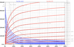
1) Ia and Ig2 curves are fitted to the Telefunken data sheet.
2) I tried also to mimic the secondary emission effect, which was hard to precisely fit. However, my thing is for sure more accurate in this aspect than all the other models which ignore secondary emission.
3) Grid model: I missed any data here, so I derived those from the next similar tube with reliable Ig1 data, which is the 6L6. the Ig1 gain factor was first unified for an exponent of 1.5 (as the 6L6 g1 model's exponent deviated from the 1.5), and then scaled linearly by the heating power of 6L6 & EL34.
Hence, please note that my EL34 g1 model provides "the right order of magnitude", say +70% / -40% or so, according to my stomach.
It is up to you whether this is sufficient for your needs.
BR Adrian
Code:
*EL34 LTspice model based on the generic tetrode/pentode model from Adrian Immler, version i4, Mar. 2020
*Be aware that the iG1 model is just guessed due to lack of iG1 data!!
*A version log is at the end of this file
*Params fitted to Telefunken datasheet by Adrian Immler, Mar. 2020
*This model is an enhancement of Adrians generic triode model to achieve tetrode/pentode behaviour.
*Hence, it is also suitable when the tetrode/pentode is "triode connected".
*Convenient for tetrodes, power beam tetrodes and g3-grounded pentodes.
*Copes secondary emission effect!
*            TE=Telefunken
*            | version i4
*            | | p=preliminary due to lack of iG1 data
*            | | | plate (in this model, "anode" means the internal virtual triode anode)
*            | | | | grid2
*            | | | | |  grid1
*            | | | | |  |  cathode
*            | | | | |  |  |
.subckt EL34.TEi4p P G2 G1 K
.params
*Parameters for the space charge current @ Vg <= 0
+ mu1 = 12.5    ;Main factor for voltage gain @ constant Ia in triode mode
+ ks = 287      ;Permeance factor. Has to be readjusted if xs is changed
+ Vg0 = 0.95    ;Offsets the Ia-traces on the Va axis. Electrode material's contact potential
+ kp = 50       ;Mimics the island effect
+ xs = 1.48     ;Determines the curve of the Ia traces. Typically between 1.2 and 1.8
*
*Parameters for an optional space charge current reduction @ Vg > 0
+ kIsr = 0.0    ;Va independable Is reduction, a function of Vg1
+ Rg1i = 10     ;Internal grid1 resistor which causes an extra Is drop when Va approaches zero.
*
*Parameters for assigning the space charge current to Ia and Ig @ Vg > 0 and small Va
+ kB1 = 0.1     ;Describes how fast Ia_virtual drops to zero when Va_virtual approaches zero.
+ radl = 50     ;Differential resistance for the Ia emission limit @ very small Va and Vg > 0
+ tsh = 12      ;Ia transmission sharpness from 1th to 2nd Ia area. Keep between 3 and 20. Start with 20.
+ xl = 1.3      ;Exponent for the emission limit
+ Vctl = 0 f=0  ;Offsets the Ia emission limit trace on the Va axis. f=related Vg1 koeff.
*
*Parameters of the grid-cathode vacuum diode
+ kg1 = 2k5     ;estimated value!!
+ Vctg1 = 0.55  ;estimated value!!
+ xg1 = 1.5     ;Determines the curve of the Ig slope versus (positive) Vg and Va >> 0
+ VT = 0.1      ;Log(Ig) slope @ Vg<0. VT=k/q*Tk (cathodes absolute temp, typically 1150K)
*
*Parameters for the caps
+ cg1p  = 1p1   ;according datasheet
+ cg1All= 15p2  ;according datasheet
+ CpAll = 8p4   ;according datasheet
+ Cpk  = 0p1    ;not mentioned in datasheet
*
*Parameters to enhance the triode model to a pentode model
+ mu2 = 30      ;1/mu2 is the fraction of Vp which together with Vg2i builds the virtual Triode-Anode Voltage
+ kB2 = 0.045   ;Describes how fast Ip drops to zero when Vp approaches zero.
+ Rg2i = 10     ;Internal grid2 resistor. Causes an Is reduction when Ig2 increases while Vp drops
+ fr2 = 0.02    ;determines the residual ig2 fraction @ high Va values
+ ftfr2 = 8m    ;if fr2 showes a Vg2 dependancy, this can be considered with this parameter
*
*Parameters to mimic the secondary emission (inspired from Derk Reefmans approach)
+ co = 1.4      ;decribes the crossover region (Ise drop when Va increase). between 0 and 9
+ Vse=60   a=0  ;Va where the sec. emission is strongest. a=related Vg1 coefficient
+ Ise0=12m b=0m8;sec. emission peak current @ Vg=0. b=related Vg1 coefficient
+ Vg2ref = 360  ;Vg2 where the following coeffficients has no influence to the emission effect:
+ c = 10m       ;Vg2 coefficient of a
+ d = 30m       ;exp Vg2 coefficient of Ise0
+ e = 2u5       ;Vg2 coeff. of b
*
*Calculated parameters
+ kl = pow(1/(radl*xl*Ild**(1-1/xl)),-xl) ;Reduces the xl influence to the Ia slope @ small Va
+ Ild = sqrt(radl)*1m ;Current where the limited anode a.c. resistance is set according to radl.
*
*Space charge current model
Bggi GG1i 0 V=v(G1i,K)+Vg0 - v(G1,K)*(1-1/(1+kIsr*max(0,v(G1,K)))) ;Effective internal grid voltage.
Bahc Ahc 0 V=uramp(v(P,K)/mu2+v(G2i,K)) ;voltage of the virtual triode anode, hard cut to zero
Bst St 0 V=max(v(GG1i)+v(Ahc)/(mu1), v(Ahc)/kp*ln(1+exp(kp*(1/mu1+v(GG1i)/(1+v(Ahc))))));Steering volt.
Bs Ai K I=1/ks*pow(v(St),xs) ;Langmuir-Childs law for the space charge current Is
*
*Anode current limit @ small Va
.func smin(x,y,n) {pow(pow(x + 1f, -n)+pow(y+1f, -n), -1/n)} ;Min-function with smooth trans.
Ra A Ai 1
Bpl G2i P I=i(Rp) - smin(1/kl*pow(v(P,K)+min(0,Vctl+f*v(G1,K)),xl),i(Rp),tsh);Ip emission limit
*
*Grid model
Rg1i G1 G1i {Rg1i} ;Internal grid resistor for "Ia-reduction" @ Vg > 0
.func Ivd(Vvd, kvd, xvd, VTvd) {1/kvd*pow(VTvd*xvd*ln(1+exp(Vvd/VTvd/xvd)),xvd)} ;Vacuum diode function
Bg1vd G1 K I=Ivd(v(G1,K)+Vctg1-1m*sqrt(v(Ahc)), kg1, xg1, VT) ;Grid-cathode vacuum diode
Bg1r G1i Ai I=ivd(v(GG1i),ks, xs, 0.8*VT)/(1+kB1*v(Ahc));Is reflection to grid when Va appr. zero
Bs0 Ai K I=ivd(v(GG1i),ks, xs, 0.8*VT) - 1/ks*pow(v(GG1i),xs) ;Compensates neg Ia
*@ small Va and Vg near zero
*
*additional model parts necessary for a pentode
Rg2i G2 G2i {Rg2i}
Rp P A 1
Bg2r G2i A I=i(Ra)*((1-frg2())/(1+kB2*max(0,v(P,K))) ) ; Va dependable ig2 part, reflected from the plate
Bg2f G2  A I=i(Ra)*frg2() ; Va independable ig2 part. Not to lead this current over Rg2i improves convergence
.func frg2() {fr2*exp(ftfr2*(v(G2,K)-250))}
*
*model for secondary emission effect
*nomalizing function nf(sh) ensures that the peak of y=x*(1-tanh(sh(x-1)) is always at x=1 while sh=0..9
.func nf(z) {609m/z + 293m + 107m*z - 5.71m*z*z}
.func sh() {pow(co,2)} ;results in a more linear control of the cross over region with the param co
Bsee G2 P I=min(Ise()*nf(sh())*xf()*(1-tanh(sh()*(nf(sh())*xf()-1))) / (nf(sh())*(1-tanh(sh()*(nf(sh())-1)))),i(Rp)-i(Bpl))
.func Ise() {smin(uramp(Isef() - bf()*v(G1,K)),0.98*i(Rp),2)} ;avoides neg. Iplate caused by strong sec. em.
.func xf() {v(P,K)/(1m+uramp(Vse-af()*v(G1,K)))}; moves the sec emission peak to the wanted voltage Vsep
.func af() {a + c*(v(G2,K)-Vg2ref)}
.func Isef()   {Ise0 * exp(d*(v(G2,K)-Vg2ref))}
.func bf()  {b + e*((v(G2,K)-Vg2ref))}
*
*Caps
C1 G1 P {cg1p}
C2 G1 K {(cg1All-cg1p)/2} ;As this model does not consider the ambient as further electrodes for parasitic caps,
;best way is to assume this " g1 to all" cap as it would be half to cathode and half to g2 (after substraction of cg1p).
C3 G1 G2 {(cg1All-cg1p)/2}
C4 P K {cpk}
C5 P G2 {cpAll-cpk-cg1p}
.end
*
*Version log
*i1 :Initial version
*i2 :Pin order changed to the more common order "P G2 G1 K" (Thanks to Markus Gyger for his tip)
*i3 :residual ig2 @ large Va introduced; 2nd emission effect introduced;
;Va indep. grid current parts no longer lead over internal grid resistors for better convergence
*i4 :to improve convegence, the Ia reduction @ pos Vg is no longer done by Rg1i. Instead, kIsr introduced
;Furthermore, ks and Vg0 are set directly, as rad and Vct turned out to be usefull for triodes only
*i4f :Major bug fixed. Tube works now also when Cathode not grounded (for cathode follower and the like)
Attachments
or simply use Moglia's 6E5P model instead, basically the same tube ...The 6E6P model returns the error message below. Is anyone aware of an alternate pentode mode version? Thanks.
https://www.bartola.co.uk/valves/2014/01/26/6e5p-beam-tetrode-spice-model/
Attachments
Thanks! Appreciated. Will give both a spin.I tried to fix the inconsistencies
Hi Adrian,
thank You very much; i'll give it a try.
Specifically, i have setup a spice simulation of the power stage of the Dynacord Eminent 2. I observed a strong dependency of the available bias voltage on the grid leak resistors. Same effect in a G-2000 which is 10 years younger. Which can be caused by (a) significantly leaking coupling caps and (b) the G1 current caused by G1 collecting electrons. Or both, but at least in the G2000 i tested the caps ok when i restored the amp (put another one in series, no measurable effect on the potentials)
I would like to decrease those resistors - they are a bit out of spec even for the EL34 - and ran into trouble attempting this.
BTW: the 6L6 requires for much smaller grid leak resistances than the EL34, and also the KT77 has slightly stronger demands on the grid leaks, according to the data sheet. It looks to me as if that might be a property of beam power tetrodes in general, although i do not see the reason).
thank You very much; i'll give it a try.
Quite possible.It is up to you whether this is sufficient for your needs.
Specifically, i have setup a spice simulation of the power stage of the Dynacord Eminent 2. I observed a strong dependency of the available bias voltage on the grid leak resistors. Same effect in a G-2000 which is 10 years younger. Which can be caused by (a) significantly leaking coupling caps and (b) the G1 current caused by G1 collecting electrons. Or both, but at least in the G2000 i tested the caps ok when i restored the amp (put another one in series, no measurable effect on the potentials)
I would like to decrease those resistors - they are a bit out of spec even for the EL34 - and ran into trouble attempting this.
BTW: the 6L6 requires for much smaller grid leak resistances than the EL34, and also the KT77 has slightly stronger demands on the grid leaks, according to the data sheet. It looks to me as if that might be a property of beam power tetrodes in general, although i do not see the reason).
Did you try Mogliaa's ... it worked for me last time I used it.Well, thanks again but no luck with either. Can't vouch for the curve fit, the only model that runs is Bench's 6e5p attached.
https://www.bartola.co.uk/valves/2014/01/26/6e5p-beam-tetrode-spice-model/
I get similar msg when I copy / paste from the web site into LTspice.
Copy / paste from web pages seems to introduce some garbage characters.
Here's the version I used (and tested just a couple of minutes ago w/o problems).
Unpack the .inc file as is directly from the zip ...
Copy / paste from web pages seems to introduce some garbage characters.
Here's the version I used (and tested just a couple of minutes ago w/o problems).
Unpack the .inc file as is directly from the zip ...
Attachments
Mhmm, it gives me an (unspecific) undefined subcircuit, using the xpentode4 symbol :-(It is up to you whether this is sufficient for your needs.
BR Adrian
You need to use the LTspice built-in tetrode symbol. Most "pentode" tubes are actually modeled as tetrodes.

My LTSPICE installation (ltspice4, linux, wine) provides pentode, tetrode and xpentode4 symbols.
xpentode4 describes a pentode with internally connected suppressor grid and hence has the same pins as the tetrode. Accordingly, both symbols lead to the identical problem, an undefined subcircuit without further specification. Both symbols run without technical problems with all the other EL34/KT77 models i have tested (Koren, Ayumi) and also give identical results for a given other model.
Which means the problem must be somewhere in Adrian's model. Maybe a cut and paste error. Unfortunately the download link on Adrian's website is gone
- which is a pity, because the circuitry i am testing is an old industrial design where also measurements of important values for an .op analysis is available (i hacked the Dynacord Eminent 2 power stage into LTSPICE, but do not dare to post it here due to the well known aversion of the maintainers against PA circuitries even if these are often used for hifi purposes nowadays.)
1.) Pin name parameters (sequence) not equal in symbol and include file.
Samples in include files:
.SUBCKT F2a_t P G2 G K ; LTSpice tetrode.asy pinout
.SUBCKT F2A_P P G K G2 ; Koren Pentode Pspice pinout
tetrode.asy contains 1:Anode, 2:Screen (G2), 3:Grid (G), 4:Cathode sequence
2.) *.sym file contains
SYMATTR ModelFile ......
registry.
If the latter happened, the sym file working only with such file (for example tetrode.txt), which is defined in ModelFile registry.
Well, i mentioned the Ayumi model was working. That one is conforming to the ltspice tetrode (and xpentode4) pinouts, and it works.
I took the Koren model from two libs (the old TubeLib.lib and a variant of that containing some small signal triode models derived from µTracer-measurement in addition to the Koren stuff) which were adopted to LTSPICE and which do also work.
That's why i suspect some sort of cut'n paste error and would rather like to see a return of the download link which seems to have disappeared from Adrian's page.
EDIT: sometimes it might help to check the error log:
occurs repeatedly.
I took the Koren model from two libs (the old TubeLib.lib and a variant of that containing some small signal triode models derived from µTracer-measurement in addition to the Koren stuff) which were adopted to LTSPICE and which do also work.
That's why i suspect some sort of cut'n paste error and would rather like to see a return of the download link which seems to have disappeared from Adrian's page.
EDIT: sometimes it might help to check the error log:
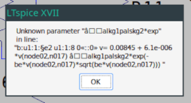
Questionable use of curly braces in "bsee g2 p i=min(((pow(pow((uramp(((ise0)exp((d)(v(g2,k)-(vg2ref))))-((b)+(e)((v(g2,k)-(vg2ref))))*v(g1,k)))+1f,-(2))+pow((0.98*i(rp))+1f,-(2)),-1/(2))))(609m/((pow((co),2)))+293m+107m*((pow((co),2)))-5.71m*((pow((co),2)))((pow((co),2))))(v(p,k)/(1m+uramp((vse)-((a)+(c)(v(g2,k)-(vg2ref)))*v(g1,k))))(1-tanh((pow((co),2))((609m/((pow((co),2)))+293m+107m((pow((co),2)))-5.71m*((pow((co),2)))((pow((co),2))))(v(p,k)/(1m+uramp((vse)-((a)+(c)(v(g2,k)-(vg2ref)))*v(g1,k))))-1)))/((609m/((pow((co),2)))+293m+107m((pow((co),2)))-5.71m*((pow((co),2)))((pow((co),2))))(1-tanh((pow((co),2))((609m/((pow((co),2)))+293m+107m((pow((co),2)))-5.71m*((pow((co),2)))*((pow({co},2))))-1)))),i(rp)-i(bpl))"
Error: undefined symbol in: "[co]"
Fatal Error: Undefined subcircuit:
occurs repeatedly.
Last edited:
continuing the questionable code snippet from the model:
Unfortunately i am not sufficiently familiar with the syntax of spice code and feel unable to fix that. Please remember: i am still running ltspice4/wine, mostly because of the annoing changes of the paths with ltspice17 which makes it really laborious to move from my initial spice/mac installation.
Code:
*Parameters to mimic the secondary emission (inspired from Derk Reefmans approach)
+ co = 1.4      ;decribes the crossover region (Ise drop when Va increase). between 0 and 9

...

.func sh() {pow(co,2)} ;results in a more linear control of the cross over region with the param co
Bsee G2 P I=min(Ise()nf(sh())*xf()(1-tanh(sh()(nf(sh())*xf()-1))) / (nf(sh())(1-tanh(sh()*(nf(sh())-1)))),i(Rp)-i(Bpl))
Unfortunately i am not sufficiently familiar with the syntax of spice code and feel unable to fix that. Please remember: i am still running ltspice4/wine, mostly because of the annoing changes of the paths with ltspice17 which makes it really laborious to move from my initial spice/mac installation.

That's why assume some kind of transfer error. Honestly, i cannot immagine, that Adrian would publish some models with syntax errors.
After transferring the model text again, everything is working for me as well. Technically - everything beyond would be OT for this thread.
diff -c even showed me the error (a stray x two lines above my quote)
So thank You for the model, dear Adrian, and all for the help.
diff -c even showed me the error (a stray x two lines above my quote)
Code:
520> diff -c EL34_Immler*mod
*** EL34_Immler_2.mod   2024-01-30 15:10:54.893934904 +0100
--- EL34_Immler.mod     2024-01-30 14:50:09.963683645 +0100
***************
*** 50,57 ****
  + mu2 = 30      ;1/mu2 is the fraction of Vp which together with Vg2i builds the virtual Triode-Anode Voltage
  + kB2 = 0.045   ;Describes how fast Ip drops to zero when Vp approaches zero.
  + Rg2i = 10     ;Internal grid2 resistor. Causes an Is reduction when Ig2 increases while Vp drops
! + fr2 = 0.02    ;determines the residual ig2 fraction @ high Va values
! + ftfr2 = 8m    ;if fr2 showes a Vg2 dependancy, this can be considered with this parameter
  *
  *Parameters to mimic the secondary emission (inspired from Derk Reefmans approach)
  + co = 1.4      ;decribes the crossover region (Ise drop when Va increase). between 0 and 9
--- 50,57 ----
  + mu2 = 30      ;1/mu2 is the fraction of Vp which together with Vg2i builds the virtual Triode-Anode Voltage
  + kB2 = 0.045   ;Describes how fast Ip drops to zero when Vp approaches zero.
  + Rg2i = 10     ;Internal grid2 resistor. Causes an Is reduction when Ig2 increases while Vp drops
! + fr2 = 0.02    ;dOBetermines the residual ig2 fraction @ high Va values
! x+ ftfr2 = 8m    ;if fr2 showes a Vg2 dependancy, this can be considered with this parameter
  *
  *Parameters to mimic the secondary emission (inspired from Derk Reefmans approach)
  + co = 1.4      ;decribes the crossover region (Ise drop when Va increase). between 0 and 9
***************
So thank You for the model, dear Adrian, and all for the help.
Odd because I'm pasting into a plain text editor that worked for the 6ag5. That last attempt was closer. No errors this time, the sim just refused start. It doesn't seem to like the cascade mosfet load.I get similar msg when I copy / paste from the web site into LTspice.
Not a big concern, the 6AG5 promises such performance in my application as to warrant bench investigation. Thanks for the assistance.
- Home
- Amplifiers
- Tubes / Valves
- Vacuum Tube SPICE Models