Hi All. I just found this forum and I am just getting started with LTSpice for tube amp modeling, and I noticed in message #2 there is a downloadable file of vacuum tube spice models already configured for LTSpice. That is great. But this thread is 175 pages long, so I don't think I will be readying the entirety of this thread to see what else in in there... so my question is this:
Is that downloadable file the entirety of the models that are available, or are there more scattered throughout the 175 pages in this thread?
Is that downloadable file the entirety of the models that are available, or are there more scattered throughout the 175 pages in this thread?
Maybe someone especially the user of the model can put together the models tested working after all that matters. It's not good enough to zip up if the models have not being tested or verified, and forum discussions (which may take a long time) become necessary to ensure the model is usable. But you can do a search in the forum for models you want, search this forum using ".subckt ecc88" give you the models results.
Attachments

Yes, there are probably hundreds of other models in this thread. After all, posting tube models is what this thread is all about.Is that downloadable file the entirety of the models that are available, or are there more scattered throughout the 175 pages in this thread?
True, but I was just wondering if just maybe someone here was keeping an ongoing repository of the models as they get posted and discussed - now wouldn't that have been nice.
But then it wouldn't be DIY (do it yourself), would it? 😉
Seriously, I can't think of any reason that I would need to have a copy of every model posted in this thread. It's not about building a model collection, but having the models that I actually need. As Koonw pointed out, the forum's search feature is your friend.
Some of the folks on the forum are very responsive when a member asks for a model that isn't posted somewhere, so if you need a specific model then this is the place to ask.

One reason is efficiency and economy of effort. "IF" there were an ongoing repository then I could download it once and find whatever I need, as opposed to mining through posts in a forum...but that's fine, searching will work.
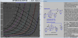
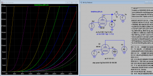
6К13П 6k13p model:
Code:
**** 6K13P3 ******************************************
* Created on 02/20/2023 21:23 using paint_kip.jar
* www.dmitrynizh.com/tubeparams_image.htm
* Plate Curves image file: 6k13p3.png
* Data source link: <plate curves URL>
*----------------------------------------------------------------------------------
.SUBCKT 6K13P P G2 G K ; LTSpice tetrode.asy pinout
* .SUBCKT 6K13P P G K G2 ; Koren Pentode Pspice pinout
+ PARAMS: MU=296.66 KG1=40.97 KP=96.64 KVB=1191.1 VCT=-0.3698 EX=0.7768 KG2=68.6 KNEE=0.93 KVC=2.732
+ KLAM=2E-6 KLAMG=3.996E-5 KNEE2=44.81 KNEX=19630.08  KNK=-0.044 KNG=0.006 KNPL=50 KNSL=11 KNPR=120 KNSR=29
+ CCG=3P CGP=1.4P CCP=1.9P VGOFF=-0.6 IGA=3E-6 IGB=0.0651 IGC=19.16 IGEX=3.124
* Vp_MAX=300 Ip_MAX=32 Vg_step=2 Vg_start=0 Vg_count=11
* X_MIN=74 Y_MIN=34 X_SIZE=795 Y_SIZE=531 FSZ_X=1296 FSZ_Y=736 XYGrid=true
* Rp=1400 Vg_ac=20 P_max=2.5 Vg_qui=-10 Vp_qui=300
* showLoadLine=n showIp=y isDHP=n isPP=n isAsymPP=n isUL=n showDissipLimit=y
* showIg1=y isInputSnapped=y addLocalNFB=n
* XYProjections=n harmonicPlot=y dissipPlot=n
* UL=0.43 EG2=90 gridLevel2=y addKink=y isTanhKnee=y advSigmoid=n
*----------------------------------------------------------------------------------
RE1  7 0  1G    ; DUMMY SO NODE 7 HAS 2 CONNECTIONS
E1   7 0  VALUE=  ; E1 BREAKS UP LONG EQUATION FOR G1.
+{V(G2,K)/KP*LOG(1+EXP((1/MU+(VCT+V(G,K))/SQRT(KVB+V(G2,K)*V(G2,K)))*KP))}
RE2  6 0  1G    ; DUMMY SO NODE 6 HAS 2 CONNECTIONS
E2  6 0  VALUE={(PWR(V(7),EX)+PWRS(V(7),EX))} ; Kg1 times KIT current
RE21 21 0 1
E21  21 0 VALUE={V(6)/KG1*ATAN((V(P,K)+KNEX)/KNEE)*TANH(V(P,K)/KNEE2)} ; Ip with knee but no slope and no kink
RE22 22 0 1 ; E22: kink curr deviation for plate
E22  22 0 VALUE={V(21)*LIMIT(KNK-V(G,K)*KNG,0,0.3)*(-ATAN((V(P,K)-KNPL)/KNSL)+ATAN((V(P,K)-KNPR)/KNSR))}
G1   P  K  VALUE={V(21)*(1+KLAMG*V(P,K))+KLAM*V(P,K) + V(22)}
* Alexander Gurskii screen current, see audioXpress 2/2011, with slope and kink added
RE43 43 K 1G ; Dummy
E43  43 G2 VALUE={0} ; Dummy
G2   43 K  VALUE={V(6)/KG2*(KVC-ATAN((V(P,K)+KNEX)/KNEE)*TANH(V(P,K)/KNEE2))/(1+KLAMG*V(P,K))-V(22)}
RCP  P K  1G     ; FOR CONVERGENCE
C1   K G  {CCG}  ; CATHODE-GRID 1
C2   G P  {CGP}  ; GRID 1-PLATE
C3   K P  {CCP}  ; CATHODE-PLATE
RE23 G 0 1G
GG G K VALUE={(IGA+IGB/(IGC+V(P,K)))*(MU/KG1)*
+(PWR(V(G,K)-VGOFF,IGEX)+PWRS(V(G,K)-VGOFF,IGEX))}
.ENDS
*$
Attachments
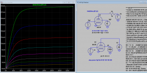
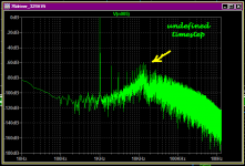
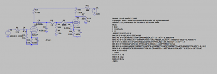
I have been converting to the Ayumi models from Rydel and Koren models, and and have run into a strange problem with the 76 model. In a simple circuit it gives near 2%thd at 1vrms out. The second harmonic shows 20dB below 3rd, which is not how the tube actually performs.
IIRC, when I actually tested a 76, it had less than 0.1% thd at 1vrms out.
Does anyone see what I am doing wrong?
IIRC, when I actually tested a 76, it had less than 0.1% thd at 1vrms out.
Does anyone see what I am doing wrong?
Attachments
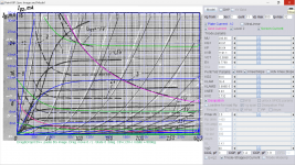
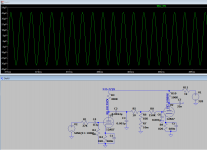
You have to set a "Maximum Timestep" if you plot that many periods of a signal.I have been converting to the Ayumi models from Rydel and Koren models, and and have run into a strange problem with the 76 model. In a simple circuit it gives near 2%thd at 1vrms out. The second harmonic shows 20dB below 3rd, which is not how the tube actually performs.
IIRC, when I actually tested a 76, it had less than 0.1% thd at 1vrms out.
Does anyone see what I am doing wrong?
If you leave it open, LTSpice takes short cuts and picks a default which is too coarse, causing quantzing errors.
(Remember, LTSpice is still "SwitcherCad" and optimized to cut run time of SMPS sims, not primarily analog).
If you magnify the time domain plot and watch closesly you can actually see that the curve is discontinuous and has kinks.
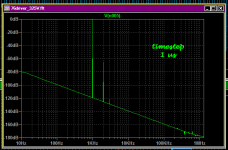
In your case, something like .tran 0 .2 .1 1u forces LTSpice to be more precise ... at the expense of run time, of course ...
With that I get THD of 0.055 %
Attachments
Last edited:

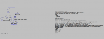
The instance name of the triode in your schematic must match the subcircuit name in your SPICE model. This is the line in the model that reads ".SUBCKT 12AX7 A G K." The model name is just 12AX7. So in your schematic, change "Generic triode model: 12AX7" to just "12AX7."
As a side comment, the schematic has no plate load resistor so there can be no output signal as the schematic is drawn.
As a side comment, the schematic has no plate load resistor so there can be no output signal as the schematic is drawn.
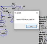
The first seven (7) lines in the Ayumi 12AX7 model are comments but your model implies that they are something else. Each line of a comment must begin with an asterisk (*). Try replacing your model with this:
Code:
* Generic triode model: 12AX7
* Copyright 2003--2008 by Ayumi Nakabayashi, All rights reserved.
* Version 3.10, Generated on Sat Mar  8 22:41:09 2008
*             Plate
*             | Grid
*             | | Cathode
*             | | |
.SUBCKT 12AX7 A G K
BGG   GG   0 V=V(G,K)+0.59836683
BM1   M1   0 V=(0.0017172334*(URAMP(V(A,K))+1e-10))**-0.2685074
BM2   M2   0 V=(0.84817287*(URAMP(V(GG)+URAMP(V(A,K))/88.413802)+1e-10))**1.7685074
BP    P    0 V=0.001130216*(URAMP(V(GG)+URAMP(V(A,K))/104.24031)+1e-10)**1.5
BIK   IK   0 V=U(V(GG))*V(P)+(1-U(V(GG)))*0.00071211506*V(M1)*V(M2)
BIG   IG   0 V=0.000565108*URAMP(V(G,K))**1.5*(URAMP(V(G,K))/(URAMP(V(A,K))+URAMP(V(G,K)))*1.2+0.4)
BIAK  A    K I=URAMP(V(IK,IG)-URAMP(V(IK,IG)-(0.00058141055*URAMP(V(A,K))**1.5)))+1e-10*V(A,K)
BIGK  G    K I=V(IG)
* CAPS
CGA   G    A 1.7p
CGK   G    K 1.6p
CAK   A    K 0.5p
.ENDSIn LTspice and in others as far as I know:
1m = 1 milliohm or one thousandth (10-3) of an ohm, abbreviated as mΩ.
1meg = 1 megaohm or one million ohms.
1m = 1 milliohm or one thousandth (10-3) of an ohm, abbreviated as mΩ.
1meg = 1 megaohm or one million ohms.
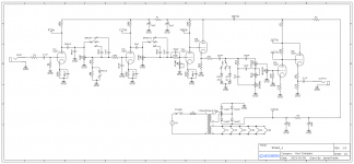
As cogncogs pointed out, the "m" prefix means "milli" or 1/1000 in LTspice. I assume that R2 and R12 in your schematic are intended to be 1 megohms, not 1 milliohms. Same with R7. So R2 and R12 should have a value of 1meg, not 1m, and R7 should be 10meg, not 10m.
At 1 milliohms, R12 is practically a short circuit. This is why you are getting almost no output voltage.
At 1 milliohms, R12 is practically a short circuit. This is why you are getting almost no output voltage.
Last edited:
The repository in post #2 is not maintained, I just don't have the time to do it. There are a lot of good models in it, and useful as a starting point. As suggested in an earlier post use the search tools to find the models for the tubes you need that are not in that library. (Last updated 5 years ago.)
- Home
- Amplifiers
- Tubes / Valves
- Vacuum Tube SPICE Models