Years of work ? Come on, let's keep our feet on the ground. We are not talking about developing the atomic bomb.........
you have no idea how much work time and money Allen Wright put into this 'concept'
and you might experience him the most stubbern and determined man you had ever met
but ofcourse you are absolutely right too
might be worth to note that in the days when the design of this amp begun, there was not the same sharing and spread of knowledge like we see it today
meaning, it was a lot more difficult and harder
its a concept
unfortunetely it was almost over before it begun
too complicated, very expencive, and not really needed
a bit like a stillborn child
as shame really
not sure, but I think it was one of the first hifi designs of this kind
and its already a vintage classic
hell, I dont know why I say this , and not even sure its true at all, but in this case I think it is
blondes have more fun
AFAIK, there is no HF oscillations caused by the heaters. DC elevation of the heaters is a good thing to do and it's mentioned in Allen's schematics. LM317 is fine as either voltage or current regulator for the heaters.
you can have HF garbage sneaked through mains xformer etc.
anyway - as I wrote - LM317 is up to task if other conditions are fulfilled ;
to name them - no HF going from rectifier , heater potential elevated to proper voltage , so heater -cathode diode leak is on adequate part of characteristic curve
then 317 is good enough
CCS is not as easy as mentioned if we need a CVS first !
Do you think Allan were gone this way ?
CCS + CVS ?
certainly not ; there is no need for that , for indirectly heated tubes
If anyone needs PCBs for the Manfred Huber rev. D shuntreg. to be used with the RTP3, PM me.
Note that the PCB is pre-mounted with some SMD components to make the design very compact.
Note that the PCB is pre-mounted with some SMD components to make the design very compact.
If any of you RTP builders want some matched 25k 5W dale resistors, please PM me.
But if you need some matched 2sk369V's you better PM me
building pre
Konichiwa, hajime mashite.
Attachments

Oops, skipped a letter.
In that case, the picture is of Mr Katsutaro Anzai, founder of Zaika audio.
= (an)Zai + Ka(tsutaro)
In that case, the picture is of Mr Katsutaro Anzai, founder of Zaika audio.
= (an)Zai + Ka(tsutaro)
Vaccum State FVP5 preamp clone
Hello,
I plan to built a Vaccum State FVP5 preamp clone.I would try to do it at close as possible to the original one. That means to use the best parts and the best lay out and the best wiring.
I think it’s one of the best peamp ever built.
I only focus my attention to the line section because don’t need the phono section.
Description : the schematic looks quite easy but I must be very carefully during the building to make it stable.
See the attached schematic.
First question: As you can see 2 of the output valves from the output stage are biaised at 100V.
What would be the best valve combination :
* Imput stage valve + CCS valve of the same channel
* Combine the R+L input stage ?
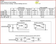
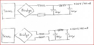
I need a 250 V/ 100mA HV Power supply with following structure: Transformer + bridge + input choke and pi filter + regulation.
The Lundahl LL1628 with 2 coils should be my final choice.
What is the way to connect them ?
· 2 coils in serie => 10H on B+
· 1 coil (5H) on B+ and one in ground (5H)
See on attached files
What do you mean with the resistor (100 Ohm) on the ground ?
Please can someone help me to calculate the chokes values ?
Hello,
I plan to built a Vaccum State FVP5 preamp clone.I would try to do it at close as possible to the original one. That means to use the best parts and the best lay out and the best wiring.
I think it’s one of the best peamp ever built.
I only focus my attention to the line section because don’t need the phono section.
Description : the schematic looks quite easy but I must be very carefully during the building to make it stable.
See the attached schematic.
First question: As you can see 2 of the output valves from the output stage are biaised at 100V.
What would be the best valve combination :
* Imput stage valve + CCS valve of the same channel
* Combine the R+L input stage ?
I need a 250 V/ 100mA HV Power supply with following structure: Transformer + bridge + input choke and pi filter + regulation.
The Lundahl LL1628 with 2 coils should be my final choice.
What is the way to connect them ?
· 2 coils in serie => 10H on B+
· 1 coil (5H) on B+ and one in ground (5H)
See on attached files
What do you mean with the resistor (100 Ohm) on the ground ?
Please can someone help me to calculate the chokes values ?
Attachments
* Imput stage valve + CCS valve of the same channel
This is best, since the late Allen recommended not to use 1 dual tube for both channels.
The Lundahl LL1628 with 2 coils should be my final choice.
Lundahl LL1628 is an excellent choice.
Your best option is 2 coils in series => 10H on B+
OK Joshua
That means one dual tube for : input stage + CCS from the second stage
Another dual tube for the Cathode follower + CVS
Same for second channel
Am I right ?
What do you think about a 100 Ohms on the ground line ?
vince
That means one dual tube for : input stage + CCS from the second stage
Another dual tube for the Cathode follower + CVS
Same for second channel
Am I right ?
What do you think about a 100 Ohms on the ground line ?
vince
OK Joshua
That means one dual tube for : input stage + CCS from the second stage
Another dual tube for the Cathode follower + CVS
Same for second channel
Am I right ?
Yes, you are correct.
What do you think about a 100 Ohms on the ground line?
Which resistor are you referring to?
Please see my attached schematic.
The resitor I mention, is on the foot of the xformer.
vince
I'm not clear about what you are trying to do.
You can do either LC filtering or RLC filtering.
Since you are going to use Lundahl LL1628 in series configuration, LC is good option for filtering mains ripple.
Adding R is useful only if want to lower the voltage. If you use R, better have the same resistor on the (+) and (-) lines.
Hi vtr,
Having read your comment on replacing the LM329 with a 9 Volt battery as a sonical improvement I wonder if that can be done without any other changes i.e. a LM329 de-
livers 6.9 Volt whereas your batteries will give 9 Volt. So are there no more changes
required? Thanks
Having read your comment on replacing the LM329 with a 9 Volt battery as a sonical improvement I wonder if that can be done without any other changes i.e. a LM329 de-
livers 6.9 Volt whereas your batteries will give 9 Volt. So are there no more changes
required? Thanks
RTP3D PS simulation...
Hi,
I just made a duncanamps PSU simulation:
The Superreg needs minimum 50V headroom.
So the PS should deliver 350V.
I Got the hint what to use: 420V Powersupply, 160mA 10H Lundahl choke + 3 x 60uF Motorcaps and 2x 47R Resistor.
I made the simulation, but never reached 350V. I need at least 440VAC from the transformer...
Attached my simulation. Does the supereg require only 330V??? What is my bloody mistake here???
Regs, Dirk
Attachments
I get 350,9V out from your simulation fileHi,
I just made a duncanamps PSU simulation:
The Superreg needs minimum 50V headroom.
So the PS should deliver 350V.
I Got the hint what to use: 420V Powersupply, 160mA 10H Lundahl choke + 3 x 60uF Motorcaps and 2x 47R Resistor.
I made the simulation, but never reached 350V. I need at least 440VAC from the transformer...
Attached my simulation. Does the supereg require only 330V??? What is my bloody mistake here???
Regs, Dirk
Yes...
But I simulated with the 440V mains!
Dirk
So my question was:
Is the RTP3D using a lower voltage??? (Or do I only need around 330V input to superreg?)
But I simulated with the 440V mains!
Dirk
So my question was:
Is the RTP3D using a lower voltage??? (Or do I only need around 330V input to superreg?)
superreg will need , say , 15V of difference ( count also on regular -10% mains decrease) to work properly .
knowing that , and programmed current per superreg , go upstream and calculate voltage sags on each element in chain
that will tell you what's voltage needed at first element after Graetz
knowing that , and programmed current per superreg , go upstream and calculate voltage sags on each element in chain
that will tell you what's voltage needed at first element after Graetz
Hi Zen Mod, Vacuumstate manual claims for the need of 50volts.
If I have 420 Volts, DC simulation gives 330V, 10 % off -> 300V, I would be low around your 15 Volts...
So back to the point in question for me: 420 Volt, 160mA drawn current is around 20V to low - correct???
If I have 420 Volts, DC simulation gives 330V, 10 % off -> 300V, I would be low around your 15 Volts...
So back to the point in question for me: 420 Volt, 160mA drawn current is around 20V to low - correct???
- Home
- Amplifiers
- Tubes / Valves
- Vacuum State RTP3C