Hello folks
I would like to share my RTP-clone with You. I had a lot of inspiration from the thread (and Alex Meganns homepage, Thanks Alex!) and now its payback-time.
I have been building for more than 1½-year and one of the things that made the build take so long was that I made the cabinets myself in my garage with hobby tools - that's a one time only experience. The cabinets started out as a 1m x 2m x 4 mm raw aluminium sheet and admitted I had a little help cutting the sheet to smaller pieces and bend the side-sheets. I even learned to anodize aluminium in the process.
For the PS I had custom made (by a local firm) trafos and chokes. The areas where my PS differ from the original is (my guess) that I use a choke filter for the bias supply and I have a 9V logic supply.
The main area where my Preamp differs from the original is that it is remote controlled – haven't bought the remote yet thou. Input selection (including ground) is done with relays close to the back. The volume control is a 64-stepped relay attenuator – and to get the fixed 50k that the phono stage demands I have chosen the expensive route and ordered special value tx2575 for line resistors and to save a bit tx2352 for the ground/shunt resistors.
Firing it up I had a little problem with noise from the super reg in the channel where the elevation of the heater supply was connected and so I chose to put the elevation in the PS before the super reg and put bigger caps across the supply-legs on the AD797 up-amp in the reg and the problem was gone.
Now I only have to order a pair front plates when I have the funds🙂
Great build, Stig - well done!
I am always intrigued when I see people building their RTP3 with remote control and relays. A few years ago I had the idea that I would design and build an ultimate solid-state preamp with remote control and all the trimmings. The project went well and it worked perfectly after a few iterations of debugging. I was very proud of it, but the trouble was it sounded a bit dull and uninspiring.
Eventually I saw the light and started planning my RTP3. This time I decided this would be totally purist - no relays, no remote, and with the dual mono balance volume controls just as Allen specified. Again, in the end everything worked, but this time the sound quality was superb and I suddenly stopped any fantasising about preamps (apart from my nearly-complete current project to build an SVP as a spare). With proper switched attenuators, the dual volume controls and lack of a remote don't bother me at all.
I think I got frustrated messing around with complex circuits, though your monolithic control logic chips will always outperform my stack of separate LSTTL chips in terms of reliability. I'm sure your RTP3 sounds excellent!
Alex
Hi folks
Thanks for the compliments.
@Alex
Once again thanks for your inspirational homepage.
I have been using remote controlled preamps with relay attenuators for the past 15 years and it has always worked for me – no dull sound and I had preamps with stepped attenuators using Elma contacts for comparison. I never had the courage to design my own Logic circuit thou.
In my listening room I have approximately 7 meters from hotspot to the preamp witch is situated around the corner - a remote control is a must.
My preamp is very god sounding and very very transparent - for the first time I heard that my Alphason HR100/VdH mc10 has a slight mechanical resonance – this simply vasen't audible before using a Aleph1.7 clone and Xono Riaa! - Cd and tuner hasn’t sounded this good before in my system.
@vtr
Allen was generous as few sharing his circuits off the best pre I ever heard. I totally agree with his statement in # 31, that those of us building his circuits owe him. I just came a bit late.
@merlin el margo:
The spec off the circuit should in the gain structure - as far as I know - bee the same as the real thing available from Vacuum State – I don't belive that the schematic off the PSU is available I used Duncans PSU designer for my edition.
Stig
Hello Folks,
I am looking for the ELMA input selector switch 2 x 12, but I can only find the 30 degree break before make version. When I review the pictures of the RTP3D it seems to me, that is should be a 15 degree version, but can't find this one in the product sheet from ELMA too?
This is the list, I have looked at: https://www.buerklin.com/default.asp?event=ShowSE()&search=13+G+1094&suggestion=&l=d&ch=85738
I thought about going for the 04-2124 version, which is 30 degrees, because I can't find the 15 degree version.
many thanks for your help
tom
Hello Folks,
I am looking for the ELMA input selector switch 2 x 12, but I can only find the 30 degree break before make version. When I review the pictures of the RTP3D it seems to me, that is should be a 15 degree version, but can't find this one in the product sheet from ELMA too?
This is the list, I have looked at: https://www.buerklin.com/default.asp?event=ShowSE()&search=13+G+1094&suggestion=&l=d&ch=85738
I thought about going for the 04-2124 version, which is 30 degrees, because I can't find the 15 degree version.
many thanks for your help
tom
Hi Tom,
I agree that the RTP3D appears to use the 15-degree switch, but I used the 30-degree one (04-2124, as you say).
Alex
herrstagl,
The original Elma selector switch supplied by Allen with the RTP3D was version 04-1210 and indeed was a 15 degree switch as shown here in a probably old data sheet:
04-1210-20 PDF Datasheet - ELMA Electronic Inc. - Datasheets360.com
This switch was std. delivered as a shorting switch but could be received on request in a non shorting version.
So if Elma doesn't manufacture this version anymore ( don't know though ) you probably will have to take the 30 degree version.
airtangent
Hello,
many thanks for the hints. I'll try to find the 04-1213, or 04-1210. We will see. 🙂
cheers, tom
many thanks for the hints. I'll try to find the 04-1213, or 04-1210. We will see. 🙂
cheers, tom
@herrstagl
Tom.
I used the Elma 04-4121 in mine. 04-4121 Datasheet - ELMA Electronic Inc. - Datasheets360.com
Michael Percy Audio has them for $110. Page 13 of his catalogue, near the bottom. http://www.percyaudio.com/Catalog.pdf
Hope this helps!
Tom.
I used the Elma 04-4121 in mine. 04-4121 Datasheet - ELMA Electronic Inc. - Datasheets360.com
Michael Percy Audio has them for $110. Page 13 of his catalogue, near the bottom. http://www.percyaudio.com/Catalog.pdf
Hope this helps!
It wasn't the relays that gave the poor sound. Reed relays work very well for me on my FVP5 without dulling the sound.
Shoog
Shoog
2wice
Not that difficult to understand.
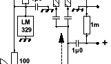
The LM329 is a precision voltage reference like a zener diode.
Have a look at the data sheet: http://www.ti.com.cn/cn/lit/ds/symlink/lm329.pdf
It's task here is to provide a stable 6.9 Volt bias for the grids of the tubes.
According to the data sheet the device is delivered in a TO-92 style package with 3 legs.
However actually only two are used with leg 3 connected to ground and 2 connected to the positive supply.
Here in this older schematic a 1k resistor is connected to 15 Volt at one side and to the LM329 at the other side in order to set the voltage to 6.9 Volt.
airtangent
Not that difficult to understand.
The LM329 is a precision voltage reference like a zener diode.
Have a look at the data sheet: http://www.ti.com.cn/cn/lit/ds/symlink/lm329.pdf
It's task here is to provide a stable 6.9 Volt bias for the grids of the tubes.
According to the data sheet the device is delivered in a TO-92 style package with 3 legs.
However actually only two are used with leg 3 connected to ground and 2 connected to the positive supply.
Here in this older schematic a 1k resistor is connected to 15 Volt at one side and to the LM329 at the other side in order to set the voltage to 6.9 Volt.
airtangent
2wice
The latest version of the RTP3D phono preamp with some hints on operation from Allen Wright can be found here at the very bottom of that page:
http://www.diyaudio.com/forums/analogue-source/154210-mpp-47.html
Basically it is the same circuit with the constant current sources feeding the lower part of the cascodes shown here and some slight changes.
Differences are the use of bipolars rather than Jfets in the lower part of the cascodes to achieve more gain and lower noise and a revised RIAA network in order to be able to use more common available capacitor values.
The LM329 is now fed from the regulated high voltage ( 300V ) by means of R24/25.
airtangent
Does the phone stage still match up to the line stage as per the VS website?
Or has there also been any changes to that also?
Or has there also been any changes to that also?
2wice
I'm pretty sure that the revised phono stage will still match up to the line stage as given on the VS website since the basic concept is still the same.
Probably there are also slight changes in the line stage since the schematic given is from 2000. However they are nowhere published in the internet as far as I know although I assume the basic schematic will still be the same here as well like in the phono amp.
Don't know what your intention is, otherwise I would advise to contact Vacuumstate wrt
to questions on the latest version of the RTP3D.
airtangent
Thanks for your help.
My intention, atm is to learn the schematic capture software and how and why this implementation is held in such high regard, and at a later stage to try and build it. I have no equipment or funds to do this any justice atm. And if I wanted to build this in a hurry I would just use the French PCB and modify it to get closer to Allen's recommendation.
So just looking for the how and why.
I'm going to try and get the book I think.
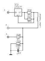
IC2 is CCS for heaters , giving I=1V25/(8R2||8R2)=304mA
good for PCC88 (7DJ8)
for ECC88(6DJ8) recalculate R26,R27 for approx. I=365mA , having in mind to achieve 6V3 across hot heater
elevated from ground on potential (node 3 ) of Ub x (R29\R28)
R26,R27 need to be at least 1/2W each , other two plain 1/4W ones
good for PCC88 (7DJ8)
for ECC88(6DJ8) recalculate R26,R27 for approx. I=365mA , having in mind to achieve 6V3 across hot heater
elevated from ground on potential (node 3 ) of Ub x (R29\R28)
R26,R27 need to be at least 1/2W each , other two plain 1/4W ones
Last edited:
- Home
- Amplifiers
- Tubes / Valves
- Vacuum State RTP3C