…
Plus, I have ordered four new (from ebay, I know) tubes claimed to be good to see if there is difference.
…
Why from eBay (if I may ask)?
Hi mishak.
VR1 looks to me as if it's used to balance the second stage. It doesn't seem to have enough adjustment to alter the gain much but I'll stand corrected on that. Have you checked anode voltages as you tweak VR1?
You are correct, VR1 (and VR2 in the right channel) are for the balancing left and right channels gain. After adjustment I measured 83 and 83 volts on anodes of left channel 83.7 and 82.4 on anodes of right channel. It is more that mentioned in schematics 60 V (don't know why, regulated supply provided +212 V instead +200, that is only 5% increase), but withing typical 90V anode voltage recommended in specification. As for the mismatch 83.7 / 82.4, I will try to modify VR1, R24, R25, R37 to have middle ground and independent adjustment for two triodes.
On the first stage, am I correct in thinking that the switch SW-2 is for setting up the input for either MM or MC?
Correct, it gives exactly 20 dB gain that I measured. It'll be replaced with front gain switch with more gain settings (40, 42, ..50, 54, 60). SW4 is for SE/BAL and input impedance setting. That switch will be replaced also with the rotary switch on the front panel, but only after I will make everything else works fine.
could you replace either R8 or R9 with a 500ro pot to balance up the stage and see if the noise level drops?
Good idea. I'll try first to modify a second stage to see if it makes any difference.
Last edited:
well built
but a phono stage at this level and bandwith should avoid the transformer, so if the heater elevation and the grid stopper increase doesn´t help i would pull out the transformer and check again
(my rtp 3 had hum problems when in the rack was the leak tuner underneath with 30cm distance....)
but a phono stage at this level and bandwith should avoid the transformer, so if the heater elevation and the grid stopper increase doesn´t help i would pull out the transformer and check again
(my rtp 3 had hum problems when in the rack was the leak tuner underneath with 30cm distance....)
and i use all sort of tubes-old new and never had hum issues ....
Hi VTR, that is a bad question, and I did not want to be impolite, but
What was your actual hum measurement? It is never a zero hum, it is always something. Mine is not too bad either. I cannot hear it from my listening position with music level of 80 - 90 dB, and I have to stick my ear into the speaker to detect it without oscilloscope.
I just want to make a reasonable assessment before making any dramatic changes as moving power supply out.
Hi mishak.
This will make you feel better! I've just measured mine and I'm getting around -50db to -55db noise and that's using 2 super regulators and a separate PSU. I think it should be you giving me advice. 😀
To reduce your B+ could you not just use an easy fix like a bleed resistor. Not very eco-friendly but would work and cheaper than changing anode resistors. Is your current source in the second stage giving 14 ma, looks like that could be down a bit and nearer 13ma.
Last tip from me, don't stick your ear in the speaker, it will be a lot quieter!!!
Hi mishak.
This will make you feel better! I've just measured mine and I'm getting around -50db to -55db noise and that's using 2 super regulators and a separate PSU.
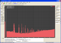
Here is mine attached. The strange thing is there are almost the same amplitude harmonics at 120,180 and 240 Hz. I found in one post a statement that 6DJ8 is famous for those harmonics, and the next reply was it is not true. I was hopping there is a possibility to theoretically identify the reason for that, or a part of schematics responsible.
I think it should be you giving me advice. 😀
I wish.😱 I have studied and was good in tube schematics, about 40 years ago. Now it's all gone. Looking for somebody to explain me.
To reduce your B+ could you not just use an easy fix like a bleed resistor. Not very eco-friendly but would work and cheaper than changing anode resistors. Is your current source in the second stage giving 14 ma, looks like that could be down a bit and nearer 13ma.
Do I actually need it?
Last tip from me, don't stick your ear in the speaker, it will be a lot quieter!!!
Two beers always work for me.
Attachments
not impolite
i never tested with spectrum analyzer, but with a scope in 1mV/cm i can detect no hum only noise and this is tube depending (for example i had a batch of tesla gold grid 88er new and all went noisy after 3 month of use-so 3 times the usual noise and my fully balanced system started with popping noise when i switched on the sldering iron or the fridge started..)
but at the output of the system should be no visible hum in the 1mv area-and i amplify wit a 20db gain 300b pp amp and with no music there is no hum to detect with the ear at the membrane of my 95db altec.
so you have done a good job so far and first step should be the heater, tube do all stupid things with a floating heater, and the maybe testwise remove the transformer-my leak tuner underneath gave me audible hum in the system, beside the rtp not.
Hi VTR, that is a bad question, and I did not want to be impolite, but
What was your actual hum measurement? It is never a zero hum, it is always something. Mine is not too bad either. I cannot hear it from my listening position with music level of 80 - 90 dB, and I have to stick my ear into the speaker to detect it without oscilloscope.
I just want to make a reasonable assessment before making any dramatic changes as moving power supply out.
Here is mine attached. The strange thing is there are almost the same amplitude harmonics at 120,180 and 240 Hz.
Is there coaxial cable for the input signal at least?

Is there coaxial cable for the input signal at least?
Hi Salas,
I don't know what you mean. Outside of the box RCA is shorted to the ground for the hum test. Inside of the box all wires, about 10 cm each, are coaxial (shielded), long runs in output are silver coated also.
I meant to ask exactly that. I.e if shielded coax is used indeed so to exclude the field hum pick up on weak signal runs. Could be a ground loop. Is there a picture of the circuit's back that can show the GND nodes?
with a scope in 1mV/cm i can detect no hum only noise ...
but at the output of the system should be no visible hum in the 1mv area-and i amplify wit a 20db gain 300b pp amp and with no music there is no hum to detect with the ear at the membrane of my 95db altec.
VTR, that is amazing result, but before I kill myself, please, confirm: with that scope setting at 1mV/cm your MM phono cartridge signal from pick to pick cover about 14 cm, equal to 14 mV, or 5 mV effective AC?
And with that input signal applied your output at the same point where you observed your noise is about 1.5 V sine from pick to pick? (40 dB amplification)
I am asking b/c my scope observation is quite different. Just want to make a proper comparison.
I meant to ask exactly that. I.e if shielded coax is used indeed so to exclude the field hum pick up on weak signal runs. Could be a ground loop. Is there a picture of the circuit's back that can show the GND nodes?
No, I was so excited assembling it that forgot to take pictures of the board from both sides. Do it for sure when I disassemble it next time.
About ground loop. That would be too easy. I tested it old fashion way, poking my finger everywhere with less then 100 V on it 🙂, and watching scope signal for change. It looks like design and my implementation is solid. There were some small problematic areas that I fixed. Plus, I tried to remove first tube to confirm that hum is coming from the second stage, at least partially.
The key feature of my problem is that hum changes when I change a tube. It looks for me as it is associated with tube itself more than with anything else.

Back in post #410 I see a hybrid BJT-tube cascoded balanced input stage. Is it driven balanced?
if you are patient
because i changed apartement and my rtp sits actual in a box and the audio system is not in operation (first i have to make the 3 phase 400V power supply working in the new basement, so 1 to 2 weeks delay until i can measure
my setup is near full gain on phono (cartridge is a low output mc benz mikro) and 20db gain in the line stage 20-26 db gain in power amp, when switching from line to phono i only hear a higher noisefloor-no hum
VTR, that is amazing result, but before I kill myself, please, confirm: with that scope setting at 1mV/cm your MM phono cartridge signal from pick to pick cover about 14 cm, equal to 14 mV, or 5 mV effective AC?
And with that input signal applied your output at the same point where you observed your noise is about 1.5 V sine from pick to pick? (40 dB amplification)
I am asking b/c my scope observation is quite different. Just want to make a proper comparison.
because i changed apartement and my rtp sits actual in a box and the audio system is not in operation (first i have to make the 3 phase 400V power supply working in the new basement, so 1 to 2 weeks delay until i can measure
my setup is near full gain on phono (cartridge is a low output mc benz mikro) and 20db gain in the line stage 20-26 db gain in power amp, when switching from line to phono i only hear a higher noisefloor-no hum
Last edited:
>>Back in post #410 I see a hybrid BJT-tube cascoded balanced input stage. Is it driven balanced?
No. All test are done or with open balanced input, no signal, or with switch set to SE (-input grounded via C2), and +input grounded via C1 (RCA shorted). Hum results are almost the same.
No. All test are done or with open balanced input, no signal, or with switch set to SE (-input grounded via C2), and +input grounded via C1 (RCA shorted). Hum results are almost the same.
Problem fixed
Just wanted to report some results.
First, thank you all for input and good advises.
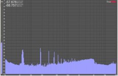
Today I tried a few fixes. First, I tested heater schematics. That was a direct hit. Even with simple connection of heater ground with common circuit ground via 0.22 uF capacitor lowered main 60 Hz harmonic by more than 10 dB, and totally removed 120 and 240 Hz harmonics (picture 1, compare to the spectrum in the post #427). Maybe applying +40 V would lower it even more, but I did not try it yet.
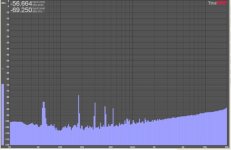
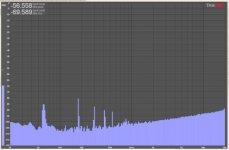
Then I tried a new (better) set of tubes I bought recently on ebay. It gave me additional 4 dB (picture 2). Finally, I tried to put screens in different places. Screen on the tube itself did not work, but screen over power transformer lowered hum by another 1 - 2 dB (picture 3).
That would be it for now.
I think I have an answer to my original question. With totally disconnected (floated) heater two different tubes even with identical gain measurement would produce different hum level due to the different physical position of the heater in relation to cathode inside of each tube.
Just wanted to report some results.
First, thank you all for input and good advises.
Today I tried a few fixes. First, I tested heater schematics. That was a direct hit. Even with simple connection of heater ground with common circuit ground via 0.22 uF capacitor lowered main 60 Hz harmonic by more than 10 dB, and totally removed 120 and 240 Hz harmonics (picture 1, compare to the spectrum in the post #427). Maybe applying +40 V would lower it even more, but I did not try it yet.
Then I tried a new (better) set of tubes I bought recently on ebay. It gave me additional 4 dB (picture 2). Finally, I tried to put screens in different places. Screen on the tube itself did not work, but screen over power transformer lowered hum by another 1 - 2 dB (picture 3).
That would be it for now.
I think I have an answer to my original question. With totally disconnected (floated) heater two different tubes even with identical gain measurement would produce different hum level due to the different physical position of the heater in relation to cathode inside of each tube.
Attachments
Last edited:
nice but please
make a elevated voltage, not to stress the heater cathode isolation and to block the micro diode between heater and cathode, 30-40V is fine with a voltage divider from filtered B+ and some capacitance.
the differences you see is due to different constuction and tolerances of tubes
klaus
make a elevated voltage, not to stress the heater cathode isolation and to block the micro diode between heater and cathode, 30-40V is fine with a voltage divider from filtered B+ and some capacitance.
the differences you see is due to different constuction and tolerances of tubes
klaus
Just wanted to report some results.
First, thank you all for input and good advises.
Today I tried a few fixes. First, I tested heater schematics. That was a direct hit. Even with simple connection of heater ground with common circuit ground via 0.22 uF capacitor lowered main 60 Hz harmonic by more than 10 dB, and totally removed 120 and 240 Hz harmonics (picture 1, compare to the spectrum in the post #427). Maybe applying +40 V would lower it even more, but I did not try it yet.
Then I tried a new (better) set of tubes I bought recently on ebay. It gave me additional 4 dB (picture 2). Finally, I tried to put screens in different places. Screen on the tube itself did not work, but screen over power transformer lowered hum by another 1 - 2 dB (picture 3).
That would be it for now.
I think I have an answer to my original question. With totally disconnected (floated) heater two different tubes even with identical gain measurement would produce different hum level due to the different physical position of the heater in relation to cathode inside of each tube.
- Home
- Amplifiers
- Tubes / Valves
- Vacuum State RTP3C