Hello Kim
Nice tip about the e-choke. From the paper about the E-choke it seems to outperform the ”oldfashoned” choke in a CLC filter.
As the E-choke has a cap in the input have you tried to use the e-choke in a choke input filter (LCLC where CL equals a E-choke)?
In my own RTP-project the e-choke may com in handy as a inline choke as i have a mains transformer delivering 480Vac and need to drop som voltage.
Your own build looks fantastic – I for one would like to see some more pictures🙂
Best regards
Stig
The E-Choke is not really designed for use in an LC filter. It really was intended for C-L-C use. There is nothing new about it, its just a "garden variety" gyrator with a MOSFET as the active device.
Cheers,
Ian
Attachments
The E-Choke is not really designed for use in an LC filter. It really was intended for C-L-C use. There is nothing new about it, its just a "garden variety" gyrator with a MOSFET as the active device.
Cheers,
Ian
i personally wouldn't touch one with a barge pole - a very weak regulator with a nasty sound signature compared to a real choke. I feel fairly confident in saying that Allen Wright would agree.
Shoog
Shoog,
Is this opinion or actual listening experience?
It is not any sort of a regulator, weak or otherwise, but used within its limitations it should provide good inductive impedance and ripple suppression.
Theory is here:
Active Choke for Valve Amplifiers
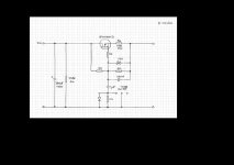
This shows that the schem above acts like a choke with:
Inductance of 1M x 10R x 100nF = 1 Henry
Series resistance of 10 x (1 + 1M/1M) = 20 Ohms
PROVIDING that the Time OFF mode is selected. IN Time ON mode the gyrator action is divided by 10 by the 100nF/1uF divider and the entire circuit swaps to a mostly capacitance multiplier operation (Multiplying that 1uF).
With the 1M, 1M parallel 100nF , 15V zener arrangement in Gyrator Mode (TIME OFF) then you can see that the gyrator will tolerate a maximum of 15V pk-pk across it which means that the input voltage must be meet that spec (<15V pk-pk ripple). Thats why it won't be any good for an L-C arrangement but is good for C-L-C arrangement.
I will be trying them out in the next power amp build. for my current SVP2 clone preamp build I have a "real" choke for an L-C style supply.
Cheers,
Ian
Is this opinion or actual listening experience?
It is not any sort of a regulator, weak or otherwise, but used within its limitations it should provide good inductive impedance and ripple suppression.
Theory is here:
Active Choke for Valve Amplifiers
This shows that the schem above acts like a choke with:
Inductance of 1M x 10R x 100nF = 1 Henry
Series resistance of 10 x (1 + 1M/1M) = 20 Ohms
PROVIDING that the Time OFF mode is selected. IN Time ON mode the gyrator action is divided by 10 by the 100nF/1uF divider and the entire circuit swaps to a mostly capacitance multiplier operation (Multiplying that 1uF).
With the 1M, 1M parallel 100nF , 15V zener arrangement in Gyrator Mode (TIME OFF) then you can see that the gyrator will tolerate a maximum of 15V pk-pk across it which means that the input voltage must be meet that spec (<15V pk-pk ripple). Thats why it won't be any good for an L-C arrangement but is good for C-L-C arrangement.
I will be trying them out in the next power amp build. for my current SVP2 clone preamp build I have a "real" choke for an L-C style supply.
Cheers,
Ian
Its a form of capacitance multiplier. Every time I tried one of those it sounded real nasty. Introduced a real bloat to the overall sound of the amp. I consistently use chokes where ever I can now and avoid power supply regulators.
Shoog
Shoog
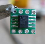
ANALOG DEVICES SSM2212RZ
Hi Alex.
Finally got the phono boards sorted! I replaced the 2SK170BL's with the SSM2212's from Farnell and, taking your advice, changed the current source resistors to 500 ohm pots. I'd originally had 330 ohm resistors in there, as per the schematic, which I'd later paralleled to 165 ohm to get more gain, without success! I have had to take the pots down to 50 ohms to get sufficient gain, around 40db, for my MM cartridge. This resistance does seem a little low for that gain but the tubes may be tired. I'll try a few different ones now it's working. Incidentally, I don't think this was the cause of the original problem as I'd tried it shorted and still didn't get the gain I needed. What resistance have you got in there?
Also replaced 330 ohm grid stoppers with 1K0's and placed 330pf caps across the input as recommended by Allen.
I also discovered that I'd had a moment of madness and put in 2 x 47K resistors at the input so I've corrected this and put in a pair of 24K9's instead. (close enough for now for the 47K0 cartridge load) The layout is more logical now with shorter paths from input to SSM2212/tubes, and I've tweaked current and pots to get 65 volts at the anodes. The voltages were slightly unbalanced before and were up around 72 volts.
All in all it's sounding good but I'll leave it to burn in a while before I try the AD797 swap in the regulators.
Having problems attaching pics to this post so I'll try later.
Regards, Dean
Very nice.
I'm intrigued by your gain problem with the phono stage. As a quick check, you could connect a pair of reasonably well-matched BC550s to see if the solid-state devices are the cause. This design is optimised for bipolar input transistors, rather than JFETs.
Have you measured the DC voltages on the anodes and cathodes of the valves? Is the standing current correct?
Alex
Hi Alex.
Finally got the phono boards sorted! I replaced the 2SK170BL's with the SSM2212's from Farnell and, taking your advice, changed the current source resistors to 500 ohm pots. I'd originally had 330 ohm resistors in there, as per the schematic, which I'd later paralleled to 165 ohm to get more gain, without success! I have had to take the pots down to 50 ohms to get sufficient gain, around 40db, for my MM cartridge. This resistance does seem a little low for that gain but the tubes may be tired. I'll try a few different ones now it's working. Incidentally, I don't think this was the cause of the original problem as I'd tried it shorted and still didn't get the gain I needed. What resistance have you got in there?
Also replaced 330 ohm grid stoppers with 1K0's and placed 330pf caps across the input as recommended by Allen.
I also discovered that I'd had a moment of madness and put in 2 x 47K resistors at the input so I've corrected this and put in a pair of 24K9's instead. (close enough for now for the 47K0 cartridge load) The layout is more logical now with shorter paths from input to SSM2212/tubes, and I've tweaked current and pots to get 65 volts at the anodes. The voltages were slightly unbalanced before and were up around 72 volts.
All in all it's sounding good but I'll leave it to burn in a while before I try the AD797 swap in the regulators.
Having problems attaching pics to this post so I'll try later.
Regards, Dean
Hello Gents,
based on a statement of Alan "When you're done, check it. Then, let someone else check it" I like to ask if there would be someone who reviews my PCBs for SuperReg, Tape Out Buffer and Power Supply.
Many thanks for your help in advance. 🙂
regards, tom
based on a statement of Alan "When you're done, check it. Then, let someone else check it" I like to ask if there would be someone who reviews my PCBs for SuperReg, Tape Out Buffer and Power Supply.
Many thanks for your help in advance. 🙂
regards, tom
Came here late, not sure if anybody watching this thread anymore, but I will shoot my question anyway.
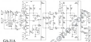
I have built a similar to RTP3 design phono preamp (based on Lite Audio made GA31 boards, the same as Allen’s originated from old HP oscilloscope schematics as I was told). Works well, good sound, etc.
But there is a small (about -60dB) hum, which is moving from channel to channel along with different tubes as I roll them. So here is my question: how critical that differential design to the matching each half of the tube(s)? Not critical at all, needs 10% tolerance, need 1% matching?
Is it possible that some hum/noise would be originated from a different gain of the upper and lower triodes with respect to the floating ground?
Appreciate any comments.
based on my rtp experience
if there is something strange as hum thats sometimes there or noise or microfonic tubes-its oszillating
do you have grid stoppers everywhere? try to increase to 5-10k and check if the moving hum is gone, and a clean earth layout with proper star grounding helps alot, for phone i asssume you have dc heaters, and i never matched tubes-of course i check if the node voltages are similar and adjust the cs to be identical
Came here late, not sure if anybody watching this thread anymore, but I will shoot my question anyway.
I have built a similar to RTP3 design phono preamp (based on Lite Audio made GA31 boards, the same as Allen’s originated from old HP oscilloscope schematics as I was told). Works well, good sound, etc.
But there is a small (about -60dB) hum, which is moving from channel to channel along with different tubes as I roll them. So here is my question: how critical that differential design to the matching each half of the tube(s)? Not critical at all, needs 10% tolerance, need 1% matching?
Is it possible that some hum/noise would be originated from a different gain of the upper and lower triodes with respect to the floating ground?
Appreciate any comments.
Hum
Hi VTR,
thank you for your response. Maybe you can give more specific advise using schematics attached?
That is a printed board already grounded in one point only, heaters are DC, voltages are fine.
Key feature is it is a low hum with equal spectrum at 60, 180 and 240Hz that is changing as I replace a bulb.
Attachments
Last edited:
schematic looks fine
i would not use all the cartridge loading stuff, btw 47uf looks too much usually its pf...
is your dc heater voltage elevated? (should be 30V above ground) with a well filtered voltage divider and then test each stage alone where the humn coms from, chassis is grounded as well?
i would not use all the cartridge loading stuff, btw 47uf looks too much usually its pf...
is your dc heater voltage elevated? (should be 30V above ground) with a well filtered voltage divider and then test each stage alone where the humn coms from, chassis is grounded as well?
Came here late, not sure if anybody watching this thread anymore, but I will shoot my question anyway.
I have built a similar to RTP3 design phono preamp (based on Lite Audio made GA31 boards, the same as Allen’s originated from old HP oscilloscope schematics as I was told). Works well, good sound, etc.
But there is a small (about -60dB) hum, which is moving from channel to channel along with different tubes as I roll them. So here is my question: how critical that differential design to the matching each half of the tube(s)? Not critical at all, needs 10% tolerance, need 1% matching?
Is it possible that some hum/noise would be originated from a different gain of the upper and lower triodes with respect to the floating ground?
Appreciate any comments.
Hi mishak.
Not what you want to hear but Allen didn't like boards for his amps however can't see why your's wouldn't work if the layout's OK. Have other builders had issues with the board or can the suppliers not advise?
FWIW I haven't matched my RTP3C tubes but I have put 2 x 22 turn 500r0 pots in to replace the 330r0 resistors. I'm using the SSM2212RZ, which btw is almost half the noise of the lm394h, and found that I had to reduce the pots to just under 100r0 to get enough gain from my 5mv MM cartridge. (you've not mentioned which cartridge you're using.) With pots you can adjust each side so that the anode voltages match. My current source is adjustable as well! I initially had noise problems on the line side, not enough gain, so I increased the gain for a better signal/noise ratio. Could this be part of the problem you're having? I also changed the 47k0 resistors to 24k0's as my cartridge is floating.
VTR makes a good point regarding grid stoppers. I started with 100r0 and increased to 1k0 but no harm in experimenting with them. You are probably aware that you need to keep the leads as short as possible at the grid. Also he mentions the caps on the input. Take a look at the RTP3C layout and you won't see any caps or those first 3 resistors!
Again, as per VTR, my dc heaters are raised. Mine are at 40v.
Alex M has got a great website The Vacuum State Electronics Realtime preamplifier documenting his build so you may pick some tips up there.
i would not use all the cartridge loading stuff, btw 47uf looks too much usually its pf...
That C2 of 47uF is not a cartridge load, it used to "screw" a first differential stage to produce a balanced output from a RCA SE input. That part is fine.
is your dc heater voltage elevated? (should be 30V above ground) with a well filtered voltage divider and then test each stage alone where the humn coms from, chassis is grounded as well?
Thank you for that point. No, DC heater is totally disconnected from the amplification stage, just regulated and filtered. I can try to connect it to the +15 V regulator used for a grid stopper, or your advise would be to make a divider connected to anode +200 ? It is well regulated and filtered, plus I added additional four 400 uF, one after each HV regulator.
Thank you for that point. No, DC heater is totally disconnected from the amplification stage, just regulated and filtered. I can try to connect it to the +15 V regulator used for a grid stopper, or your advise would be to make a divider connected to anode +200 ?
Probably either one will do, Allan made a divider from the High Voltage (+200V or +250V, depending on the model). +15V may be too low. (However, AFAIK, not elevating the heaters shouldn't cause hum).
Best is to have two 0.1u capacitors from each heater pin, connected close to the socket pins, to the ground.
It is well regulated and filtered, plus I added additional four 400 uF, one after each HV regulator.
Depending on the regulator, an electrolytic capacitor at it's output may cause instability and oscillations. It isn't recommended, not without looking with oscilloscope at the high voltage rail.
As for your hum problem, it may come from the power transformer, if it's located near the tubes. (Best is to have the PSU and the amp in two different enclosures). You can try to make small cylinders from copper foil, wrapped around each tube and grounded. It's a good practice, even when there is no audible hum.
Hi mishak.
Not what you want to hear but Allen didn't like boards for his amps however can't see why your's wouldn't work if the layout's OK. Have other builders had issues with the board or can the suppliers not advise?
Hi valve5425,
thank you for your reply.
I don't think that Allen would be concern about Lite Audio design decisions, both have roots in 50's and 60's oscilloscope designs, and I am not up to the level to make a judgment which one is better. I choose those boards (after long research), because I wanted to try a fully balanced tube phono stage. (I have/had ARC SP6B and SP16 as SE tube and PS Audio GCPH fully (?) balanced SS to compare).
And that preamp that I made is a pretty good without any tweaks. Extremely high quality build with good components. Just that tiny hum. Here is a funny part: I spent a lot of time trying to find somebody who built the same preamp using those GA31 boards, and could not fine anybody. It looks like I am the only one (after designer) in the world who actually used it. 🙂 That is why I posted my question here as the closest discussion I could find.
FWIW I haven't matched my RTP3C tubes but I have put 2 x 22 turn 500r0 pots in to replace the 330r0 resistors. I'm using the SSM2212RZ, which btw is almost half the noise of the lm394h, and found that I had to reduce the pots to just under 100r0 to get enough gain from my 5mv MM cartridge. (you've not mentioned which cartridge you're using.) With pots you can adjust each side so that the anode voltages match.
Here is the only one suspicious for me part of schematics. If you look into second stage, you can see that both cathode resistors R24 and R25 are bypassed by one trimmer VR1. Could it be a place that created some sort of positive feed back? Or that is totally stupid suggestion of mine? I can add additional trimmer in parallel to R25, and have original connected in parallel to R24, so each half of the tube would be regulated independent.
As for the input:
I am using right now for testing 5mv MM cartridge, but have a plan to make a fully adjustable from the front load selector from 10 ohm to 96 kohm for both balanced and SE inputs.
Hi Joshua,
Yes, it is possible, but I checked. And my concern is 60 Hz hum for now.
I agree with all recommendations, but here is what puzzles me most: Before starting that project I've collected some number of tubes, about 20 of NOS 6N23P and about 20 of used various Amperex Holland 6DJ8, some Bugle Boy and some PQ. Then I used a tube tester to choose 8 best tubes with 10% tolerance between halves. And when I actually tried them in working preamp, only four (two PQ and two Bugle Boys) worked well. The rest produced an audible hum. Why? Get back to my original question.
Depending on the regulator, an electrolytic capacitor at it's output may cause instability and oscillations. It isn't recommended, not without looking with oscilloscope at the high voltage rail.
Yes, it is possible, but I checked. And my concern is 60 Hz hum for now.
As for your hum problem, it may come from the power transformer, if it's located near the tubes. (Best is to have the PSU and the amp in two different enclosures). You can try to make small cylinders from copper foil, wrapped around each tube and grounded. It's a good practice, even when there is no audible hum.
I agree with all recommendations, but here is what puzzles me most: Before starting that project I've collected some number of tubes, about 20 of NOS 6N23P and about 20 of used various Amperex Holland 6DJ8, some Bugle Boy and some PQ. Then I used a tube tester to choose 8 best tubes with 10% tolerance between halves. And when I actually tried them in working preamp, only four (two PQ and two Bugle Boys) worked well. The rest produced an audible hum. Why? Get back to my original question.
I agree with all recommendations, but here is what puzzles me most: Before starting that project I've collected some number of tubes, about 20 of NOS 6N23P and about 20 of used various Amperex Holland 6DJ8, some Bugle Boy and some PQ. Then I used a tube tester to choose 8 best tubes with 10% tolerance between halves. And when I actually tried them in working preamp, only four (two PQ and two Bugle Boys) worked well. The rest produced an audible hum. Why? Get back to my original question.
It's also my experience that many NOS 6DJ8/6922 tubes are noisy and microphonic. I found out that the only safe way around it is to order tubes from Tube Depot: 6DJ8 / 6922 / ECC88 / E88CC / CV2492 Tube Types and have them tested for "Low Noise and Microphonics". (I also have pairs tested for "Balanced+Matched triodes").
Of that tubes family, from current production, I like most the Electro-Harmonix 6922. The good NOS ones are very expansive, too expansive for me.
At times there are cheaper NOS ones on eBay, alas, to my experience, many of them are actually used ones and many of them are very noisy. I poured too much money to the drain purchasing tubes on eBay. I'm not going to buy anymore tubes on eBay and I'm not going to buy anymore tubes which aren't tested for low noise and microphonics. AFAIK, only Tube Depot has such testing to tubes, both of current production and NOS.
The fact that the hum you get is dependent on the tubes you use indicates that the most probable cause for that hum is the tubes themselves. (Which doesn't preclude all other measures to attain low noise in a phono stage).
alot of answers
first i would rise the heater to 30-40V, make a voltage divider from HV and filter it well, i´ve connected mine to one leg of the heater supply.
and ok for the 47uf but if you cured the hum i would change all this stuff and rewire the phono cartridge, because the cartridge itself is a fully balanced source, why go to unsym and then back to sym, (and if i have a unsym source i would ground one input, this works well for me)-btw much better works to use the - input for ground and the + for +, gives a better rejection of noise, actually i use my rtp phono now for amplifying my dac after a 2 ohm i/V resistor......
and yes where´s your transformer?
and i use all sort of tubes-old new and never had hum issues with tubes-running a 0,2mv cartridge with mat02 and pp300b monos and 95db altec 605b speakers
Last edited:
Thank you all for comments and recommendations.
I will try some this weekend. First, rise the heater, then adjust grid voltages to match anode voltages, try variations of grounding, shield tubes, etc. Plus, I have ordered four new (from ebay, I know) tubes claimed to be good to see if there is difference.
Input schematics is fine. I can use switch SW4 in the balanced position, and the cartridge would be connected to the + and - of differential stage directly. Order does not matter b/c I am going to have a polarity switch for the input.
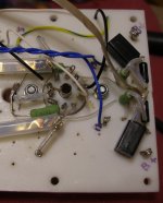
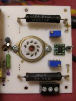
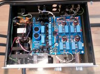
I use 100W R-Core Transformer from the same Lite Audio. Looks like a well made. See picture attached.
I will try some this weekend. First, rise the heater, then adjust grid voltages to match anode voltages, try variations of grounding, shield tubes, etc. Plus, I have ordered four new (from ebay, I know) tubes claimed to be good to see if there is difference.
Input schematics is fine. I can use switch SW4 in the balanced position, and the cartridge would be connected to the + and - of differential stage directly. Order does not matter b/c I am going to have a polarity switch for the input.
I use 100W R-Core Transformer from the same Lite Audio. Looks like a well made. See picture attached.
Attachments
Hi valve5425,
thank you for your reply.
I don't think that Allen would be concern about Lite Audio design decisions, both have roots in 50's and 60's oscilloscope designs, and I am not up to the level to make a judgment which one is better. I choose those boards (after long research), because I wanted to try a fully balanced tube phono stage. (I have/had ARC SP6B and SP16 as SE tube and PS Audio GCPH fully (?) balanced SS to compare).
And that preamp that I made is a pretty good without any tweaks. Extremely high quality build with good components. Just that tiny hum. Here is a funny part: I spent a lot of time trying to find somebody who built the same preamp using those GA31 boards, and could not fine anybody. It looks like I am the only one (after designer) in the world who actually used it. 🙂 That is why I posted my question here as the closest discussion I could find.
Here is the only one suspicious for me part of schematics. If you look into second stage, you can see that both cathode resistors R24 and R25 are bypassed by one trimmer VR1. Could it be a place that created some sort of positive feed back? Or that is totally stupid suggestion of mine? I can add additional trimmer in parallel to R25, and have original connected in parallel to R24, so each half of the tube would be regulated independent.
As for the input:
I am using right now for testing 5mv MM cartridge, but have a plan to make a fully adjustable from the front load selector from 10 ohm to 96 kohm for both balanced and SE inputs.
Hi mishak.
Apologies if it came across as criticism regarding the boards, just wondered if the layout could have been contributing to the noise. Looking at your photo it's a nice tidy build!
VR1 looks to me as if it's used to balance the second stage. It doesn't seem to have enough adjustment to alter the gain much but I'll stand corrected on that. Have you checked anode voltages as you tweak VR1?
On the first stage, am I correct in thinking that the switch SW-2 is for setting up the input for either MM or MC? Just a thought, but could you replace either R8 or R9 with a 500ro pot to balance up the stage and see if the noise level drops?
I'm running PCC88 tubes in mine at around 6.5 volts so they are not overly hot.(heaters have adjustable current sources so it's easy to swap tube types) Even so I'd be a little concerned about wrapping foil around my tubes, other than for experimental purposes, due to potential heat issues. I bow to superior knowledge on this one though! To be fair I have used tube sockets with screening cans on other gear without problems but they were designed for them. Just thought it worth a mention!
- Home
- Amplifiers
- Tubes / Valves
- Vacuum State RTP3C