Very nice.
I'm intrigued by your gain problem with the phono stage. As a quick check, you could connect a pair of reasonably well-matched BC550s to see if the solid-state devices are the cause. This design is optimised for bipolar input transistors, rather than JFETs.
Have you measured the DC voltages on the anodes and cathodes of the valves? Is the standing current correct?
Alex
Hi Alex.
I'll post some measurements when I get chance to check again. I did do some measurements a while back and everything seemed OK.
I used the jfets as per the cookbook although I realise that Allen did end up using the MAT02's as his preferred input. I'm guessing that that's where the problem lies and that something is staring me in the face. Just can't see it at the moment! Get back to you. Thanks.
Nice work Kim! Makes mine look like a bucket of spaghetti!
U did..... 😉@ Kim
I think I already saw your insane style ......... 😉
My line & RIAA module for one channel of the RTP3D (2008 instructions):
Wow - that is so neat it could almost be CGI...
It makes my RTP3 look very scruffy.
Alex
think about
upgrading to pp or something else in the hv power supply section, a must for this type of preamp
Thanks Zen Mod. It keeps the room warm as well!!
upgrading to pp or something else in the hv power supply section, a must for this type of preamp
Hi Nelson Bass,
Referring to your offer from 27.11.2011 I wonder I you still can supply PCB's for the Manfred Huber rev. D shunt regs to be used with RTP3. However can you specify first dimensions of the PCB? Could you also supply information like schematic, parts list and setup instructions for the Huber reg? And of course finally what would be the price?
Thanks and wish you a happy new year.
airtangent
upgrading to pp or something else in the hv power supply section, a must for this type of preamp
Hi VTR.
I've got polyproplylenes in the regulators, with pio's and the large electrolytics just after the rectifier. It would be nice to have all pio's but my psu's large enough as it is! TBH I thought I'd gone overboard getting the ripple down so much before the regulators, as they do get rid of virtually all of the ripple and line noise. Additionally, I thought the beauty of the differential circuit was that, provided it was well balanced, it got rid of most of the AC common mode noise which makes it less critical what you put before it.
I feel there are always compromises to make, usually relating to cash, so priorities have to be made. If shunt regulators are being used then I would start with a quality one, see what's left in the wallet for large ironwork then choose caps. As Allen Wright says "There's a point where you can't get any more filtering from capacitors, and the HF garbage will just float over the top of the big ones anyway, so get down and choke it out of existence!"
yes all the life is a compromise
but-its not expensive, go for motorstartcaps in surplus market, upgrading my superregs from elkos to mundorf mkp (standard one) was a major improvement
and you have the space for caps in your power supply
but-its not expensive, go for motorstartcaps in surplus market, upgrading my superregs from elkos to mundorf mkp (standard one) was a major improvement
and you have the space for caps in your power supply
Hi VTR.
I've got polyproplylenes in the regulators, with pio's and the large electrolytics just after the rectifier. It would be nice to have all pio's but my psu's large enough as it is! TBH I thought I'd gone overboard getting the ripple down so much before the regulators, as they do get rid of virtually all of the ripple and line noise. Additionally, I thought the beauty of the differential circuit was that, provided it was well balanced, it got rid of most of the AC common mode noise which makes it less critical what you put before it.
I feel there are always compromises to make, usually relating to cash, so priorities have to be made. If shunt regulators are being used then I would start with a quality one, see what's left in the wallet for large ironwork then choose caps. As Allen Wright says "There's a point where you can't get any more filtering from capacitors, and the HF garbage will just float over the top of the big ones anyway, so get down and choke it out of existence!"
but-its not expensive, go for motorstartcaps in surplus market, upgrading my superregs from elkos to mundorf mkp (standard one) was a major improvement
and you have the space for caps in your power supply
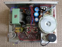
I'm a bit strapped for space in the PSU (I'll post a piccy of the completed PSU when I get time tomorrow) but I could probably get a couple of largish caps in there before the regulators. They would be lower capacitance though so ripple would go up and it may lead to some ringing, I'd have to check PSUD2. I have used motor run caps in other gear, my power amps use ASC's from Percy Audio. The Obbligato Film Oil Caps from DIYHIFI supply look OK and are the right price but I haven't tried them. They do get some good reviews though.
As for recapping the SuperRegs, they're onboard the amp chassis so space really is at a premium. Changing the LF351 op amp on the shunt to an AD797 and getting rid of the LM317T for a fixed resistor would possibly make more of difference and wouldn't need any more space. The 797's are waiting in my parts box but I just wanted to get everything else working right first!
Priority at the moment however is to get the phono board working. I'll be taking Alex M's advice and popping in a couple of BJT's to see if that makes a difference and checking some measurements. I had a quick look at it yesterday and one half of one of the valves was misbehaving so that's a start. I need to order a couple of AD SSM2212RZ's from Farnells because if I've got to take the boards out I may as well ditch the 2SK170's. Anyone else used these dual NPN, low noise, chips?
BTW Happy New Year everyone!!!
but-its not expensive, go for motorstartcaps in surplus market, upgrading my superregs from elkos to mundorf mkp (standard one) was a major improvement
and you have the space for caps in your power supply
Hi VTR.
Not too much space left!! I'll check sizes of other caps though and see what will go in. Like you say, it would be better to ditch the electrolytics.
Just in case anyone else is thinking I'd had a drink when I fitted the chokes, because they are close together they interact with each other so, with power applied, I measured the ripple and re-orientated them to get the lowest measurement. Not as neat but made quite a difference. I've found neat doesn't always make for better results!
Attachments
SSM2210/SSM2212 AND FG Elektronik
Hi,
@valve5425: I also plan to use the SSM2212. I compared the data sheets for the 2210 and 2212 and there were no noticeable differences for me. But I am not sure. Is there any parameter, which I haven't identified, which requires to change some other parts. Or can I use the SSM2212 as a replacement for the SSM2210 (that's what I expect)?
Btw. very neat build!
Some feedback regarding FG Elektronik. They do not produce custom made transformers anymore, but they kind of outsourced that business to rufa.de. I contacted them about the choke and the transformer. FG Elektronik will provide them with the coil card (not sure if that is a proper translation) if needed. Stay tuned.
regards, tom
Hi Tom.
Thanks for that, glad you like it!
The SSM2212 replaced the SSM2210, the difference being it is now SOIC (smd) package SSM2212 datasheet and product info | Audio Dual Matched NPN Transistor | Matched Transistors | Analog Devices Farnell UK have stock.
I got some SOIC - DIL adapters off EBay to make things a little easier as I've not done much with surface mount. With my eyes, valves are a bit easier to work with!
Another thread here.............. electro-music.com :: View topic - CGS VCO - replacement for the lm394/MAT-02
Regards, Dean
Hi Dean,
haha, haven't seen that tiny difference. Many thanks, found the SSM2212 on Digikey as well as the adapter. Wonderful, thank you.
Tom
haha, haven't seen that tiny difference. Many thanks, found the SSM2212 on Digikey as well as the adapter. Wonderful, thank you.
Tom
The 797's are waiting in my parts box but I just wanted to get everything else working right first!
Your RTP3 is simply stunning. Well done!
I wish you well with the AD797s, but feel I should warn you that it is quite likely that you will convert your shunt regulators into RF transmitters.
Allen was very sanguine in his advice about plugging in these sensitive and fast devices but I would advise extreme caution. Do only one board at a time and keep your oscilloscope warm.
The AD797 datasheet gives explicit instructions for power supply bypassing including making provision for a Kelvin return and ensuring the shortest possible lead lengths. The use of an IC socket is quite out of the question.
You may well be lucky but you could also find yourself, as I did, in the invidious position of having to yank out your expensive AD797s because you cannot get the regulators to stop oscillating.
Hi RTP3D builders,
I am currently starting with the planning for building and RTP3D. I red the thread, browsed the net and haven't found information about the Power Supply, but there are still a lot of unclear parts for me.
Therefore I like to ask following questions:
- I saw on the schematic a LL1628 Choke, but on some picture a LL1685.
I asked Lundahl about that, but they don't know anything about the LL1628. Some thoughts?
- Heater Choke (6mH/12mH)
I can't figure out which brand to use. Anyone any hints?
- Trafo for TR2 (100VA/420V)
Seems on the pictures like it is the same brand as the heater choke. But I can't figure out what it is
Any hints or ideas would be very welcome!
Many thanks, Tom
Hello, Tom.
I can confirm that the schematic does list the B+ choke as being LL1628, but it is definitely an LL1685, a 10H, 160mA common-mode choke.
The choke for the heaters that is no longer made by FG Elektronik was a double choke: the 6mH and 12mH windings were wound on a common core.
The label on the choke reads as follows:
TRV65/BV 3503
gn-bn=12mH 1,4A
sw-rt=6mH 2,8A
This choke buzzed very loudly and I had to abandon one of the windings. I substituted the 6mH, 2,8A winding with a Lundahl LL1694/2A choke (with the windings connected in parallel).
The 100VA/420V traffo was made by FG Elektronik. It is a double C-core.
Hi valve 5424,
Regarding your remark „To be on the safe side I've used relays to switch off the HT should any of the heater supplies fail“ I would like to ask you some questions.
Having read this I would be highly interested to see how you accomplished that.
My first question is do you mean by any of the heater supplies the two rectified DC voltages for low and high heater in the PS or do you really refer to each of the 12 CCS supplies?
There is already a relay in the power supply which switches the HT on with a certain delay after the filament voltages in the PS have come up.
However there is no provision for monitoring condition of the individual filaments during operation.
So could you tell us more in detail ( schematic and actual build up? ) how you made this?
If you really monitor each filament individually I would assume that since the filaments are fed by CCS’s you need to detect the actual voltages as measured at the filaments of each tube separately in order to check health of filaments or not?
It would definitely be a nice additional feature to have for all 12 tubes in the RTP3C/D and I can imagine that there are other users here who would be very interested as well.
Please let us know.
Thank you very much.
Best regards, airtangent
Your RTP3 is simply stunning. Well done!
I wish you well with the AD797s, but feel I should warn you that it is quite likely that you will convert your shunt regulators into RF transmitters.
Allen was very sanguine in his advice about plugging in these sensitive and fast devices but I would advise extreme caution. Do only one board at a time and keep your oscilloscope warm.
The AD797 datasheet gives explicit instructions for power supply bypassing including making provision for a Kelvin return and ensuring the shortest possible lead lengths. The use of an IC socket is quite out of the question.
You may well be lucky but you could also find yourself, as I did, in the invidious position of having to yank out your expensive AD797s because you cannot get the regulators to stop oscillating.
What would you suggest being the best alternative to AD797?
Silver foil interconnects
Hi Valve 5425,
Did you source these from VSE? If not can you advise where you got them from?
Cheers!
Ravi
Hi Valve 5425,
Did you source these from VSE? If not can you advise where you got them from?
Cheers!
Ravi
What would you suggest being the best alternative to AD797?
I don't know. I don't use Allen's SuperReg boards any more. I built instead the HPHV shunt regulators based on the Manfred Huber design. These boards use a Burr-Brown OPA655 FET-input opamp. It is a very good chip and is stable in this circuit.
- Home
- Amplifiers
- Tubes / Valves
- Vacuum State RTP3C