Hey Greg,
Thanks for the offer, I will definitely consider it if I end up saving enough money for these babies!
All the best!
Do
Do,
Looking at the kit price, it would be a fraction of the $$ to do it this way. I won't hijack this thread any more with this 😀
Cheers,
Greg
My boards arrived this morning with the charming lady on her electric 3 wheel delivery thing 😉
They look great, thanks Fab!
They look great, thanks Fab!
USSA 5.1 update
You are welcome coolnose, looking forward to seeing your build progress.
For those building the version 5.1 I have built a second channel and performed some tweakings on the input stage and driver bias currents. This has led to change the temperature compensation. For this reason, R7 and R8 should be 1K5 ohms value and also R13 and R14 should be now 22 ohms. I will provide an updated manual for the 5.1 version builders shortly. I have replaced the USSA5B with USSA5.1 in my USSA amp chassis. I have also performed some listening sessions in my main system and after a few days, as a teaser, .......................................... it appears to meet my expectations 🙂
Fab
Attachments
You are welcome coolnose, looking forward to seeing your build progress.
For those building the version 5.1 I have built a second channel and performed some tweakings on the input stage and driver bias currents. This has led to change the temperature compensation. For this reason, R7 and R8 should be 1K5 ohms value and also R13 and R14 should be now 22 ohms. I will provide an updated manual for the 5.1 version builders shortly. I have replaced the USSA5B with USSA5.1 in my USSA amp chassis. I have also performed some listening sessions in my main system and after a few days, as a teaser, .......................................... it appears to meet my expectations 🙂
Fab
A lot of bananas in that build. I'm glad the Gorilla is happy.......😀

Happy New Year 2020!
Happy new year all🙂
As another teaser of the USSA version 5.1, well after several days...................................I cannot stop listening to it
It is quite enjoyable for my personal taste 🙂
I will be waiting for feedbacks from the ones building it soon.
Fab
Happy new year all🙂
As another teaser of the USSA version 5.1, well after several days...................................I cannot stop listening to it
It is quite enjoyable for my personal taste 🙂
I will be waiting for feedbacks from the ones building it soon.
Fab
You are welcome coolnose, looking forward to seeing your build progress.
For those building the version 5.1 I have built a second channel and performed some tweakings on the input stage and driver bias currents. This has led to change the temperature compensation. For this reason, R7 and R8 should be 1K5 ohms value and also R13 and R14 should be now 22 ohms. I will provide an updated manual for the 5.1 version builders shortly. I have replaced the USSA5B with USSA5.1 in my USSA amp chassis. I have also performed some listening sessions in my main system and after a few days, as a teaser, .......................................... it appears to meet my expectations 🙂
Fab
Hi Fab
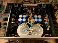
I can see a small blue box capacitor connected in series with the RCA input ground to a PCB board. What is this connection for and what is the perforated board with all those components?
Thanks
Hi Gary
I have already incorporated your comments of the manual and I received other comments today. Hopefully within a few days it will be ready 🙄
Fab
I have already incorporated your comments of the manual and I received other comments today. Hopefully within a few days it will be ready 🙄
Fab
Last edited:
Hi manniraj
The caps are installed between input RCA ground and chassis via a pcb mounting screw( in that case because it was convenient and worked fine). It reduces the background noise furthermore by creating an AC connection to chassis. DC connection to chassis from input RCA ground may create ground loops depending on the overall grounding arrangement.
The perforated pcb is simply a soft start circuit that I built many years ago before such boards were readily available on the net...
this amplifier chassis is not new and has seen many different amps over the years...😉
Fab
Last edited:
Hi manniraj
The caps are installed between input RCA ground and chassis via a pcb mounting screw( in that case because it was convenient and worked fine). It reduces the background noise furthermore by creating an AC connection to chassis. DC connection to chassis from input RCA ground may create ground loops depending on the overall grounding arrangement.
The perforated pcb is simply a soft start circuit that I built many years ago before such boards were readily available on the net...
this amplifier chassis is not new and has seen many different amps over the years...😉
Fab
Thanks Fab, I have never tried a cap on the RCA input ground to the chassis even when I had hum coming in the amplifier. Looking at your suggestion I think I will also try to make this on my amps where I get some hum. What value is the cap?
Hi manniraj
The cap value I used for that function is 100nF. The location of the connection to the chassis makes a difference too. The cap mainly reduces the « hiss « noise of the amp, not that efficient to cure a big hum problem though..unless you replace a direct DC connection to chassis causing the hum by this cap.
Fab
FSSA amp question
Hi AnthonyA
That is a good question. ECX mosfet is single die so use it only (and only in FSSA , not the USSA) for smaller power like less than 40Wrms or so. You would still need the minimum output bias of 400ma to get the possible increase of “musicality”. In fact, the FSSA should sound fine in class A at about 25Wrms or so. But for a 100-120Wrms class AB amp you need to use the double die Lateral mosfet ECW to get the intended performance into more difficult speaker load.
Good luck with your FSSA amp build.
Fab
Yes ECX is single die and ECW is double die Lateral Mosfet. If you look at respective datasheet parameters like ID, yfs, Ciss , Coss and package size talk by itself.
Double die has a big advantage over using 2 single die packages in parallel because you can expect the best possible parameters matching between the 2 internal transistors 😉
In the USSA5 the main advantage is the transconductance of the output that is doubled which can increase furthermore the open loop gain thus at the same time increases the damping factor to the required target value.
The only drawback is the max power handling capability because of smaller area to dissipate heat for double die compared to 2 independent packages🙄
Fab
Last edited:
I just completed a draft updated manual covering now the 3 variants (USSA5, USSA5.1 and USSA5B).It was already sent today to 3 members for their possible review.
The interest of the new manual is for the versions 5.1 and 5B. So for the builders intending to do versions 5.1 and 5B you can contact me by message or email.
Fab
The interest of the new manual is for the versions 5.1 and 5B. So for the builders intending to do versions 5.1 and 5B you can contact me by message or email.
Fab
Hi Fab
I received the trafos rated 19v 5A each secondary for dual mono build. I tested one of them on my CRC PSU board and I get a stable voltage of +/-28.6 vdc without any load. Hopefully this is good to go for the initial setup.
Also I have your initial manual which I have gone through multiple times so going to follow it up during my setup in the coming weekend 🙂
Thanks
- Home
- Group Buys
- USSA-5 PCB GB