Another thing: how many volts more does the booster zener have to be to consider the regulator's drop?
With the zener, there is no clean way: you will ruin some parameter.I imagine there's no way to, but can we trim the regulated voltage output on the single transistor regulator?
An adjustable reference like the TL431 could do the job, except the 431 is limited to ~30V.
If you can find a 431-like circuit withstanding 70V, it would be possible
Or the 2-transistor oneThat would certainly be a good reason to go back to the 3-transistor regulator, because we have a trimpot there.
Apparently, it requires about 10V dropout to begin to regulate.Another thing: how many volts more does the booster zener have to be to consider the regulator's drop?
Add 20% + 1V as a safety margin, and you are at 13V.
Since a higher voltage comes almost for free, use 15V to be on the safe side.
If you use the smooth, non-tracking version, the zener must be 15V higher than the highest possible V+ voltage.
The 2 and 3 transistor regulators are LDO's, and require <1V to regulate properly
With the zener, there is no clean way: you will ruin some parameter.
An adjustable reference like the TL431 could do the job, except the 431 is limited to ~30V.
If you can find a 431-like circuit withstanding 70V, it would be possible
So the resulting V+ and V- voltages would always have some difference. Which Luxman didn't seem to care, or they hand picked the zeners to null the differences.
Or the 2-transistor one
Just compared them, adding the same RC input filter to both. The two-transistor reg is still 10dB worst than the single one @ 10Hz.
Increasing to 220 ohms /1000uF decreases that, but is it worth it?
The 2 and 3 transistor regulators are LDO's, and require <1V to regulate properly
Which would be the drop with the 1 transistor reg?
In any case, would it make much of a difference, audio quality wise:
1) To have a slight difference between regulated V+ and V-?
2) To be 10dB worst at 10Hz?
3) None of them matters much.
Just for the fun of it, to see what did change, I added the capacitance multiplier used by Goldmund Mimesis 9 to the 2 transistor regulator.
This time I got -100dB at 10 Hz.
What are the pros and cons of capacitance multipliers?
This time I got -100dB at 10 Hz.
What are the pros and cons of capacitance multipliers?
Both possibilities are plausible. An asymmetry of a few % normally makes no differenceSo the resulting V+ and V- voltages would always have some difference. Which Luxman didn't seem to care, or they hand picked the zeners to null the differences.
That's unfortunate, but it is the price to be paid for the LDO, good DC performance and low output impedance.Just compared them, adding the same RC input filter to both. The two-transistor reg is still 10dB worst than the single one @ 10Hz.
Since the limiting factor is also the Early effect, you could use the same tweak as for the 3-transistor, and gaining 10dB without adjustment is probably possible, but if you want more, an individual adjustment will be necessary
I don't think soIncreasing to 220 ohms /1000uF decreases that, but is it worth it?
Around 10V, as I saidWhich would be the drop with the 1 transistor reg?
Normally 3), if the amplifier is designed correctly, but it is extremely difficult to be accurate without examining the actual circuit.In any case, would it make much of a difference, audio quality wise:
1) To have a slight difference between regulated V+ and V-?
2) To be 10dB worst at 10Hz?
3) None of them matters much.
You can stack regulators, passive & active filters ad infinitum and get -300dB PSRR, but what's the point?Just for the fun of it, to see what did change, I added the capacitance multiplier used by Goldmund Mimesis 9 to the 2 transistor regulator.
This time I got -100dB at 10 Hz.
You can find all the information on the net or this forum, but remember that cap-mults, in their simple form are just like simple regulators, except they don't regulate, and their PSRR is limited also by the Early effectWhat are the pros and cons of capacitance multipliers?
OK, things are getting to a nice closure over this power amp supply.
Let me tell you what I think it's worth using.
1) LDO, good DC performance and low output impedance are interesting. Point to the two transistor regulator.
2) Asymmetry is not essential, but easy to have with a trimpot. Point to the two transistor regulator.
3) Adding a CM adds one more transistor, but I get better specs than with the three transistor regulator. Point to the two transistor regulator with CM filtering.
The would provide me with an adjustable LDO, good DC performance and low impedance regulator. Am I right?
Yes, it a good tradeoff for a decent regulator. Being fully discrete, it will be quite robust if you chose a sufficient pass transistor. You can also add a protection transistor if required, and the circuit has not been tweaked in any way: by optimizing the bias currents, E-B resistor etc., you can certainly scrape some dB's of performance here and there.The would provide me with an adjustable LDO, good DC performance and low impedance regulator. Am I right?
Yes, it a good tradeoff for a decent regulator. Being fully discrete, it will be quite robust if you chose a sufficient pass transistor. You can also add a protection transistor if required, and the circuit has not been tweaked in any way: by optimizing the bias currents, E-B resistor etc., you can certainly scrape some dB's of performance here and there.
First of all, thanks for your help in getting here. To all of you.
Currents will be quite low for me to worry about the pass transistor being "sufficient".
How and where should I add a protection transistor, and why? I will add DC protection circuit, also inspired on the one used by Goldmund, which also protects from oscillations.
Now I will open another thread, as I had mentioned, for the RIAA preamp's power supply. And your Denoiser and NoNoise design will be main contenders.
A protection is always optional, and you could think that it is only needed in bench supplies, and you could be right -most of the times-, but it is inexpensive, easy, and can save the day when you are experimenting with your circuit, or if a cap goes short, etc.How and where should I add a protection transistor, and why? I will add DC protection circuit, also inspired on the one used by Goldmund, which also protects from oscillations
Here is an example of such a protection, dimensioned for ~60mA:
Thanks to a strange LTspice quirk, the first load is 200ohm and corresponds to the 24mA trace.
60mA is for 1K
Attachments
Great. Of course I will add the protection. Thank you.
You had also suggested optimizing bias currents and the E-B resistor. Would that show on the simulation or only with the supply working?
BTW: I did open another thread for the RIAA preamp PS, and both your D-noisator and NoNoise are on the options. If you can go have a look it would be great.
Looking for a good power supply for a RIAA preamp
There's already a sim loaded, from the original supply, but it's not running as it should, probably because some variable is wrong. The regulated output voltage is showing, but now the curves I expected.
I would like to sim those supplies for PSSR, noise and impedance, if possible. Like you did with your NoNoise.
One thing I perceive with your regulators is that they are all positive types, and I am not sure I will have separate secondaries to use two positive regs. AFAIK only 317/337 have pos and neg versions. Is that so?
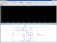
Some further investigation on the High voltage low current regulators we had been working with.
This time the theme is impedance.
Hopefully the simulating setup is correct.
Curve results are not as good as the superregulators and similar that are being analyzed on another thread.
The unsolved question is how a power supply impedance affects the audio quality. Or how PSRR or how noise does affect sound quality, particularly on this case where the signal levels we are dealing on power amps are a lot higher than on sensitive low current preamps.
Attachments
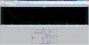
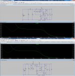
An strange case for this comparison was between these two versions of the same original two transistor regulator.
One with transistor protection and the other with a capacitance multiplier between input filter and regulator.
As it can be seen, the version with the CM behaved slightly better than the other one in impedance response.
Stranger yet, even if not shown, was that adding the CM to the protected regulator resulted in an even worst impedance response.
Attachments
Not strange at all: the series resistance has to be corrected and has a small impact on the output Z.
When you use both the CM and protection, you have the addition of the series input impedances resulting in slight degradation of the output Z
When you use both the CM and protection, you have the addition of the series input impedances resulting in slight degradation of the output Z
So you have to get to a compromise between output Z degradation and better PSRR from both regulators?
Though I wonder if this would result in audible changes for different combos.
When I first read about output impedance in a power supply in The Audio Amateur, the idea seemed to be that a wideband lower impedance on a power supply would result in a "better" audio quality. Some instead of "better" describe what they think changed, which I think is more objective.
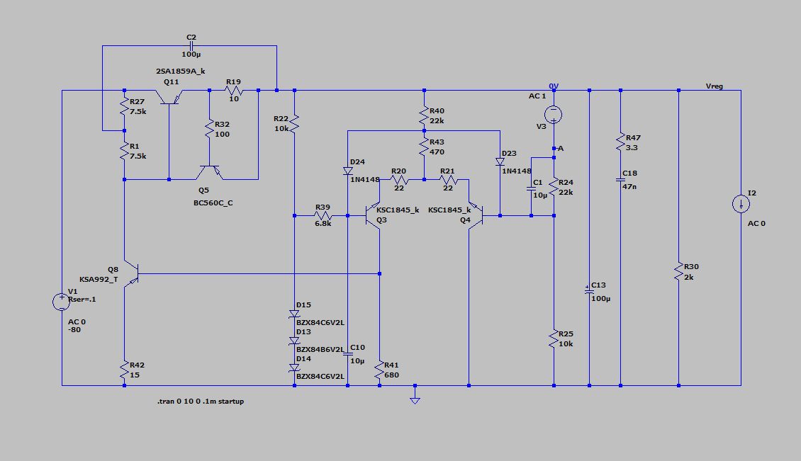
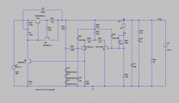
You could try something like the circuit below, it's a bit more complex than the 3 transistor circuits but will provide much lower output impedance and 90 dB line rejection in audio band. It does need some more dropout voltage for the bootstrapping to work, otherwise it can be replaced with a CCS. This is the negative version, just invert polarities and flip diodes for positive version.
Attachments
Extremely complex for a low current power supply. Not a good deal really.
Some of the work has to be done by the power amplifier itself for PSRR, and being high level voltages noise is not really an issue.
In any case, the circuit is interesting. Can you upload the asc file?
Some of the work has to be done by the power amplifier itself for PSRR, and being high level voltages noise is not really an issue.
In any case, the circuit is interesting. Can you upload the asc file?
Sure, here you go. Note that C13 includes ESR and ESL specified. The ESL comes from another thread here where people measured actual ESL of real electrolytic caps. Hence the presence of the output Zobel, without it the output could ring when stimulated with output current pulses.
If you get bored, also attached is the original design which is even more complex. I call it the Blameless regulator since it resembles Doug Self's Blameless Amplifier reconfigured for regulator service. This is more of an academic exercise at this point though I would not be surprised someone actually trying to build it. It even has two-pole-compensation! Maybe I'll put it in a new thread if people care.
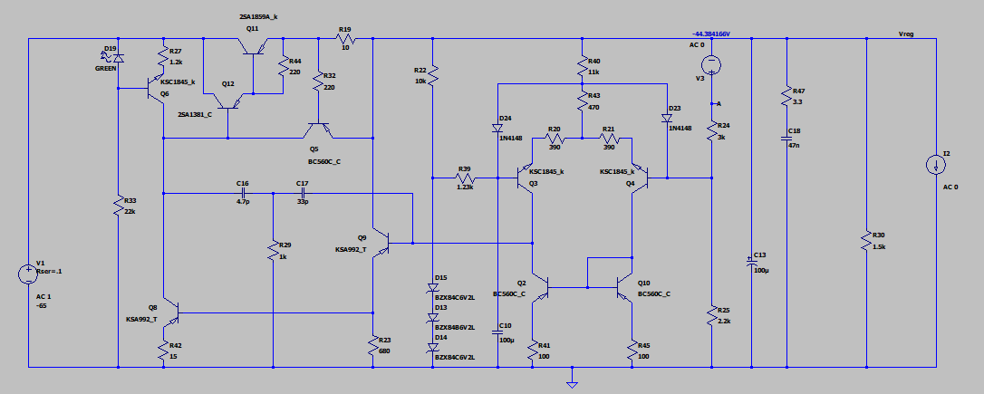
If you get bored, also attached is the original design which is even more complex. I call it the Blameless regulator since it resembles Doug Self's Blameless Amplifier reconfigured for regulator service. This is more of an academic exercise at this point though I would not be surprised someone actually trying to build it. It even has two-pole-compensation! Maybe I'll put it in a new thread if people care.
Attachments

Some further investigation on the High voltage low current regulators we had been working with.
This time the theme is impedance.
Hopefully the simulating setup is correct.
Curve results are not as good as the superregulators and similar that are being analyzed on another thread.
The unsolved question is how a power supply impedance affects the audio quality. Or how PSRR or how noise does affect sound quality, particularly on this case where the signal levels we are dealing on power amps are a lot higher than on sensitive low current preamps.
If you replace R2 by a zener and D1, D3 by a resistor and make Q1 an NPN, it'll get better.
Jan
It will trade impedance for PSRR.
What is the most important for the application Carl has in mind?
I personally have no idea since I find this type of regulator superfluous anyway
What is the most important for the application Carl has in mind?
I personally have no idea since I find this type of regulator superfluous anyway
I also think that this regulator will not work in practise as it has positive feedback in my view. It may be stable in LTspice, sometimes called metastability so it may look OK, but I would first check with a prototype.
Jan
Jan
- Home
- Amplifiers
- Power Supplies
- Using the LM317 with higher voltages