From reading the ultra-long thread on 'GON' yeah the Aeris uses the AD1853 which is I think 5 bit delta-sigma. As did the Benchmark DAC 1st edition.
Aeris DAC
That is an impressive looking dac. I will have to study that hybrid dac chip. Clearly I will never be able to afford one of those. Interesting enough I read somewhere about a DSD dac from maybe PS Audio that uses a transformer based filter. Although I might be wrong on that. 🙂Rowland Aeris Dac uses them somewhere in the analog stage.
http://www.my-hiend.com/leoyeh/2011b/IMG_9653cc.jpg
They also use the hybrid AD1853 dac, this is supposed to be so many bits multibit and delta Sigma, does anyone know?
Cheers George
Abraxilito, you up on all this new dac tech. When they say do convert PCM "bit perfect" it need to be done with a r2r multibit dac.
If that's correct this AD1853 can't claim to do all PCM "bit perfect" can it, just 5 bits of it?
Cheers George
If that's correct this AD1853 can't claim to do all PCM "bit perfect" can it, just 5 bits of it?
Cheers George
pin6 direct DC vs pin5 TZ + buffer out
well came home last night and tried this evening, from the AD844 3-stack now trimmed in input as well as offset (seem to drift a few mv) pin 6: bypass the whole buf/filter stage and output coupling caps . Well some extra detail maybe but also bit 'sharp' (in the the aggressive meaning).
Then lifting the AD844 pin 6 and soldering a cross pin on from pin5 AD844 to pin 6 position in socket. Removing the bypass wires and in with the buffer/filter opamp (LT1357 which was my best buf/filter choice up to then) but still leaving the output cap out = good real good. Detail and air and room, flow and deep body bottom. Just hastily changed the buf/filt opamp to opa1611 = made bass leaner and top brighter (not so much my taste, though it was musical enough)
well don't know if I should invest in opa627 for this buf/filter..is the impact more than subtle in your setups?
/patrick
Abraxilito, you up on all this new dac tech.
Hi George - well I've been looking into DACs for quite a number of years, not sure if I'm up to date with the very latest.
When they say do convert PCM "bit perfect" it need to be done with a r2r multibit dac.
I'd say yes that's correct - any digital processing applied whatsoever means the output's no longer 'bit-perfect'. By which I mean having identical bits to those that went in. Not that bit-perfect is required for sonic nirvana but it can't hurt can it?
If that's correct this AD1853 can't claim to do all PCM "bit perfect" can it, just 5 bits of it?
Most certainly correct, but the 'bit-perfection' is lost before the bits reach the modulator. It has oversampling filters prior to the S-D part. So even those remaining 5 bits aren't going to be the top 5 from the input datastream. Many DAC designs with the AD1853 bypass those filters though and substitute their own - those still won't be 'bit-perfect', but bit-perfect isn't necessarily a desirable goal in digital filter design. I can't see an advantage of those filters which claim to 'keep all the original samples' myself.
OPA627's
Hi Patrick, I think I understand what you did there with floating the AD844's pin 6 and a jumper within your CD player. OPA627's... With set at Gain =2. It is dynamic, fast and inner details are superb. Better then any common op amp. The ones you listed are not in my chip collection. When I applied the Lundahl based filter to my PCM1704 dac it was greatly improved. So I have settled on this configuration as the final version of this dac. Need an enclosure yet however I have bettered my previous reference by a decent margin. 😉well came home last night and tried this evening, from the AD844 3-stack now trimmed in input as well as offset (seem to drift a few mv) pin 6: bypass the whole buf/filter stage and output coupling caps . Well some extra detail maybe but also bit 'sharp' (in the the aggressive meaning).
Then lifting the AD844 pin 6 and soldering a cross pin on from pin5 AD844 to pin 6 position in socket. Removing the bypass wires and in with the buffer/filter opamp (LT1357 which was my best buf/filter choice up to then) but still leaving the output cap out = good real good. Detail and air and room, flow and deep body bottom. Just hastily changed the buf/filt opamp to opa1611 = made bass leaner and top brighter (not so much my taste, though it was musical enough)
well don't know if I should invest in opa627 for this buf/filter..is the impact more than subtle in your setups?
/patrick
Bias trim: monitor on input or at TZ or after buffer
well when I had the internal buffer from pin6 out: adjust bias and monitor at input..then trim the offset at pin6 w the 20k trimmer = two separate adjust and I could get both in place (w some drifting)
But now w TZ pin 5 routed directly out and into buffer/filter opamp = only the input bias trim is effective (though for peace in mind I trimmed the floating pin6 close to null anyway)
The thing is monitoring input (to AD844) w the 0.1mV display resolution of my DVM..I can have ½ to 1 full turn on trimmer or more for 0.1mV change (and very 'gentle' change). BUT this gives about 10mV out after the buffer/filter. Instead I can monitor directly over TZ (but DVM will likely affect it a little) and adjust to null here = very sensitive..and does NOT correspond to 0 at input (more like 0.1-0.3mV off at input). Monitoring at buffer/filt output (the DVM is at least not loading the TZ) = offset readings very very sensitive..but I can keep the offset here at around ½mV w some drifting (again does not read 0 at the AD844 input)
Well have not made listening test and don't know if it is audible..but for long term peace of mind..were is it best trim to null: before (pin 2) or after (pin 5 or buf) the AD844 3-pack?
thanks
/Patrick
PS total gain, think I have to much of it.. have not calculated / measured the buf / filter gain..but likely 2x or something (I've order OPA627 and ABEL2020 for test at this position, you say best w some gain here?). I can not turn my preamp volume knob up to more than about 9 oclock pos (30deg) for it being pretty loud (full volume range is 7-5 oclock = 330deg ) -> should I reduce resistor in TZ network or lower gain in buf/filter stage?
PPS w my Exposure VI/VII preamp I am routing CDP into TAPE input as it is so old preamp it does not have a spare line/CD labled input.. (only other labled one is tuner, where there is a tuner hooked on).. but that shouldn't matter as I guess line levels for TAPE is not meant to be lower than for other line inputs
Hi Patrick, I think I understand what you did there with floating the AD844's pin 6 and a jumper within your CD player. OPA627's... With set at Gain =2. It is dynamic, fast and inner details are superb. Better then any common op amp. .....
well when I had the internal buffer from pin6 out: adjust bias and monitor at input..then trim the offset at pin6 w the 20k trimmer = two separate adjust and I could get both in place (w some drifting)
But now w TZ pin 5 routed directly out and into buffer/filter opamp = only the input bias trim is effective (though for peace in mind I trimmed the floating pin6 close to null anyway)
The thing is monitoring input (to AD844) w the 0.1mV display resolution of my DVM..I can have ½ to 1 full turn on trimmer or more for 0.1mV change (and very 'gentle' change). BUT this gives about 10mV out after the buffer/filter. Instead I can monitor directly over TZ (but DVM will likely affect it a little) and adjust to null here = very sensitive..and does NOT correspond to 0 at input (more like 0.1-0.3mV off at input). Monitoring at buffer/filt output (the DVM is at least not loading the TZ) = offset readings very very sensitive..but I can keep the offset here at around ½mV w some drifting (again does not read 0 at the AD844 input)
Well have not made listening test and don't know if it is audible..but for long term peace of mind..were is it best trim to null: before (pin 2) or after (pin 5 or buf) the AD844 3-pack?
thanks
/Patrick
PS total gain, think I have to much of it.. have not calculated / measured the buf / filter gain..but likely 2x or something (I've order OPA627 and ABEL2020 for test at this position, you say best w some gain here?). I can not turn my preamp volume knob up to more than about 9 oclock pos (30deg) for it being pretty loud (full volume range is 7-5 oclock = 330deg ) -> should I reduce resistor in TZ network or lower gain in buf/filter stage?
PPS w my Exposure VI/VII preamp I am routing CDP into TAPE input as it is so old preamp it does not have a spare line/CD labled input.. (only other labled one is tuner, where there is a tuner hooked on).. but that shouldn't matter as I guess line levels for TAPE is not meant to be lower than for other line inputs
AD844 Stacking...
Pretty common to have some drift. Remember you have no feedback with the pin 5 TZ connection. When you consider you have 3 chips sitting on one another there is that too. Since your Arcam has a 1.5 mA source based on a transistor that should be adjusted for about zero going in to the stack. If you have the 20K null circuit try for as close to zero as you can on pin 5. Likely you won't see pin 6 and pin 5 at zero at the same position. Allow warm up before attempting adjustment. OPA627... Should be used at your filter position since this is a CD player. The ADEL2020 is a very good video op amp. It would work best at the I/V position with the original feedback in place. I really like that chip. In my tests... It out performed the AD844 using it's pin 6 buffers. Different story with an OPA627 buffer. 😉well when I had the internal buffer from pin6 out: adjust bias and monitor at input..then trim the offset at pin6 w the 20k trimmer = two separate adjust and I could get both in place (w some drifting)
But now w TZ pin 5 routed directly out and into buffer/filter opamp = only the input bias trim is effective (though for peace in mind I trimmed the floating pin6 close to null anyway)
The thing is monitoring input (to AD844) w the 0.1mV display resolution of my DVM..I can have ½ to 1 full turn on trimmer or more for 0.1mV change (and very 'gentle' change). BUT this gives about 10mV out after the buffer/filter. Instead I can monitor directly over TZ (but DVM will likely affect it a little) and adjust to null here = very sensitive..and does NOT correspond to 0 at input (more like 0.1-0.3mV off at input). Monitoring at buffer/filt output (the DVM is at least not loading the TZ) = offset readings very very sensitive..but I can keep the offset here at around ½mV w some drifting (again does not read 0 at the AD844 input)
Well have not made listening test and don't know if it is audible..but for long term peace of mind..were is it best trim to null: before (pin 2) or after (pin 5 or buf) the AD844 3-pack?
thanks
/Patrick
PS total gain, think I have to much of it.. have not calculated / measured the buf / filter gain..but likely 2x or something (I've order OPA627 and ABEL2020 for test at this position, you say best w some gain here?). I can not turn my preamp volume knob up to more than about 9 oclock pos (30deg) for it being pretty loud (full volume range is 7-5 oclock = 330deg ) -> should I reduce resistor in TZ network or lower gain in buf/filter stage?
PPS w my Exposure VI/VII preamp I am routing CDP into TAPE input as it is so old preamp it does not have a spare line/CD labled input.. (only other labled one is tuner, where there is a tuner hooked on).. but that shouldn't matter as I guess line levels for TAPE is not meant to be lower than for other line inputs
AD844 offset....
Patrick, I think it is important to remember the AD844's offset adjustment is intended to null the pin 6 output connection. Since the TZ point is before the buffer it might be difficult to make much of a difference there. If it is just a few mV's. I'd probably just accept that. There are plenty of other users who have some drift and offset. You could use a coupling cap if it is desired. I had only one build that got to about 0 mV's. It had the BF245A as a current source. Can't say that it is better then the bipolar solution in your Arcam. Or even the 2SK170 version. The problem is that each AD844 is an entity and when connected in a stack it is hard to predict if it will play nice with it's partners. How would one match AD844's? 😱
Patrick, I think it is important to remember the AD844's offset adjustment is intended to null the pin 6 output connection. Since the TZ point is before the buffer it might be difficult to make much of a difference there. If it is just a few mV's. I'd probably just accept that. There are plenty of other users who have some drift and offset. You could use a coupling cap if it is desired. I had only one build that got to about 0 mV's. It had the BF245A as a current source. Can't say that it is better then the bipolar solution in your Arcam. Or even the 2SK170 version. The problem is that each AD844 is an entity and when connected in a stack it is hard to predict if it will play nice with it's partners. How would one match AD844's? 😱
I never got down to which part of the circuit the null pins were on, Barrie Gilbert the AD844 designer said he would get back to me regarding this but never did, he did say he had to dig through his archives to find it.
Also I said way back that he was very chuffed to see what we were doing with it, as he never intended for anything to be done with pin TZ like we're doing, and it put a smile on his face to see this.
Cheers George
Also I said way back that he was very chuffed to see what we were doing with it, as he never intended for anything to be done with pin TZ like we're doing, and it put a smile on his face to see this.
Cheers George
this thread is very interesting to the point that I also am going to experiment with the use of AD844 so as it developed in the thread along with the chip 1704. A question. If I wanted to use the OPA627 as a buffer with gain = 2 what schematic should I use?
I need details. Pin 6 excluded. Output on Pin Tz. I think I understand it must be placed a R 200 K .... what Pin of OPA627?
I need details. Pin 6 excluded. Output on Pin Tz. I think I understand it must be placed a R 200 K .... what Pin of OPA627?
Last edited:
trims and LT1357->ADEL2020->OPA627->ADEL2020
Dave, yes found out that the bias input needed to steer 'all'.. if I completely nulled I got 10-20mV offset after buf/filt (Av=1½). The offset trim has very little effect in the 'right' direction..I have it all way set to +Vcc and not enough by it self.
Now w input bias trim -> output voltage offset to near null (very sensitive) the corresponding input bias reads around 0.1mV. That isn't too bad - or should it always be tried to exact null? (I figured Zin pin2 = 50 Ohm/3 and a max +/-2mA current swing from the DAC -> +/- 33mV. Here extra 0.1mV shouldn't stress DAC wrt its max limit of 75mV offset swing?)
BUT temperature drift. If I trim w open lid -> then close lid (and it gets warm in there) and play 15min or so .. output voltage has drifted to 20-40mV or so!. Then try to trim the board 'hot state' to null at output (=0.1 -0.2mV input bias) - it might stay within +/-10mV, but no guarantee (will monitor this more long term .. if impossible to hold fixed = maybe caps back, but preamp is AC coupled input so maybe not so critical in current setup)
While at it w trimmers noticed DAC +5 was 5.2V and -5 was -5.35V -> easy to put trimmers across 'R2' of LM317 and 337 -> to get voltages right (read somewhere the TDA1541 -15 vs -5 should be matched to 10V within +/-0.1V for the internal voltage reference.. I can get within the +/-0.01 which my DVM 20V range resolution provides.
The Arcam has split dig vs analogue supplies, well decoupled and small coil leading to dig. 5V etc etc. ANyway also put 10uF/25V OSCON on digital side supplies of SAA7220 + flipflop. Then also the +5 and -5V of TDA1541 AND from -5 to -15 supplies.
All sounds nice and detailed and airy - but these last changes are only very subtle compared to the IV changes (and even change of buf/filt opamp)
NOW Mouser came today w OPA627 and ADEL2020 for testing in buf/filt instead of LT1357. For each 'roll' again all the fuzz w trimming input bias vs vs output offset
First ADEL2020. More air and detail.. smooth..nice..bass has some body and is in control but not so articulate. Top refined.
Then OPA627. Bass firmer and top more presence - definately air.. yes foot stomping/involving .. BUT sound 'sharp', too bright for me = not so long term enjoyable.
Back ADEL2020 as if bass and top appear more 'anonymous' all though they definitely are there. Some how nice but not so involving/not really foot stomping = long term listenable as background.
So for now disappointed w the OPA627 . Only thing maybe to change gain in buf/filt 1½->2? (and at same time reduced TZ 1,5k->750 to get over all gain down = will alos help reduce out offset voltage). Or do I have to wait for a 'burn in effect' wrt these opamps?
/Patrick
Patrick, I think it is important to remember the AD844's offset adjustment is intended to null the pin 6 output connection. Since the TZ point is before the buffer it might be difficult to make much of a difference there. If it is just a few mV's. I'd probably just accept that. There are plenty of other users who have some drift and offset. You could use a coupling cap if it is desired. I had only one build that got to about 0 mV's. It had the BF245A as a current source. Can't say that it is better then the bipolar solution in your Arcam. Or even the 2SK170 version. The problem is that each AD844 is an entity and when connected in a stack it is hard to predict if it will play nice with it's partners. How would one match AD844's? 😱
Dave, yes found out that the bias input needed to steer 'all'.. if I completely nulled I got 10-20mV offset after buf/filt (Av=1½). The offset trim has very little effect in the 'right' direction..I have it all way set to +Vcc and not enough by it self.
Now w input bias trim -> output voltage offset to near null (very sensitive) the corresponding input bias reads around 0.1mV. That isn't too bad - or should it always be tried to exact null? (I figured Zin pin2 = 50 Ohm/3 and a max +/-2mA current swing from the DAC -> +/- 33mV. Here extra 0.1mV shouldn't stress DAC wrt its max limit of 75mV offset swing?)
BUT temperature drift. If I trim w open lid -> then close lid (and it gets warm in there) and play 15min or so .. output voltage has drifted to 20-40mV or so!. Then try to trim the board 'hot state' to null at output (=0.1 -0.2mV input bias) - it might stay within +/-10mV, but no guarantee (will monitor this more long term .. if impossible to hold fixed = maybe caps back, but preamp is AC coupled input so maybe not so critical in current setup)
While at it w trimmers noticed DAC +5 was 5.2V and -5 was -5.35V -> easy to put trimmers across 'R2' of LM317 and 337 -> to get voltages right (read somewhere the TDA1541 -15 vs -5 should be matched to 10V within +/-0.1V for the internal voltage reference.. I can get within the +/-0.01 which my DVM 20V range resolution provides.
The Arcam has split dig vs analogue supplies, well decoupled and small coil leading to dig. 5V etc etc. ANyway also put 10uF/25V OSCON on digital side supplies of SAA7220 + flipflop. Then also the +5 and -5V of TDA1541 AND from -5 to -15 supplies.
All sounds nice and detailed and airy - but these last changes are only very subtle compared to the IV changes (and even change of buf/filt opamp)
NOW Mouser came today w OPA627 and ADEL2020 for testing in buf/filt instead of LT1357. For each 'roll' again all the fuzz w trimming input bias vs vs output offset
First ADEL2020. More air and detail.. smooth..nice..bass has some body and is in control but not so articulate. Top refined.
Then OPA627. Bass firmer and top more presence - definately air.. yes foot stomping/involving .. BUT sound 'sharp', too bright for me = not so long term enjoyable.
Back ADEL2020 as if bass and top appear more 'anonymous' all though they definitely are there. Some how nice but not so involving/not really foot stomping = long term listenable as background.
So for now disappointed w the OPA627 . Only thing maybe to change gain in buf/filt 1½->2? (and at same time reduced TZ 1,5k->750 to get over all gain down = will alos help reduce out offset voltage). Or do I have to wait for a 'burn in effect' wrt these opamps?
/Patrick
Last edited:
AD844 Stacking...
Hi Patrick... Typed a long response and it is gone. So... Burn it in... Decide what sounds good to you. Which OPA627's did you get? SOIC are brighter sounding. DIP can be dark sounding. ADEL2020 I built a datasheet I/V for that so it was more or less as ideal as I could make. Drove a passive filter. Super simple. No buffers etc. You can try changing the TZ resistor to 750 Ohms. Likely your getting extra gain via the filter in the Arcam. Consider the OPA604 for the filter position if it is in your parts collection. 😉Dave, yes found out that the bias input needed to steer 'all'.. if I completely nulled I got 10-20mV offset after buf/filt (Av=1½). The offset trim has very little effect in the 'right' direction..I have it all way set to +Vcc and not enough by it self.
Now w input bias trim -> output voltage offset to near null (very sensitive) the corresponding input bias reads around 0.1mV. That isn't too bad - or should it always be tried to exact null? (I figured Zin pin2 = 50 Ohm/3 and a max +/-2mA current swing from the DAC -> +/- 33mV. Here extra 0.1mV shouldn't stress DAC wrt its max limit of 75mV offset swing?)
BUT temperature drift. If I trim w open lid -> then close lid (and it gets warm in there) and play 15min or so .. output voltage has drifted to 20-40mV or so!. Then try to trim the board 'hot state' to null at output (=0.1 -0.2mV input bias) - it might stay within +/-10mV, but no guarantee (will monitor this more long term .. if impossible to hold fixed = maybe caps back, but preamp is AC coupled input so maybe not so critical in current setup)
While at it w trimmers noticed DAC +5 was 5.2V and -5 was -5.35V -> easy to put trimmers across 'R2' of LM317 and 337 -> to get voltages right (read somewhere the TDA1541 -15 vs -5 should be matched to 10V within +/-0.1V for the internal voltage reference.. I can get within the +/-0.01 which my DVM 20V range resolution provides.
The Arcam has split dig vs analogue supplies, well decoupled and small coil leading to dig. 5V etc etc. ANyway also put 10uF/25V OSCON on digital side supplies of SAA7220 + flipflop. Then also the +5 and -5V of TDA1541 AND from -5 to -15 supplies.
All sounds nice and detailed and airy - but these last changes are only very subtle compared to the IV changes (and even change of buf/filt opamp)
NOW Mouser came today w OPA627 and ADEL2020 for testing in buf/filt instead of LT1357. For each 'roll' again all the fuzz w trimming input bias vs vs output offset
First ADEL2020. More air and detail.. smooth..nice..bass has some body and is in control but not so articulate. Top refined.
Then OPA627. Bass firmer and top more presence - definately air.. yes foot stomping/involving .. BUT sound 'sharp', too bright for me = not so long term enjoyable.
Back ADEL2020 as if bass and top appear more 'anonymous' all though they definitely are there. Some how nice but not so involving/not really foot stomping = long term listenable as background.
So for now disappointed w the OPA627 . Only thing maybe to change gain in buf/filt 1½->2? (and at same time reduced TZ 1,5k->750 to get over all gain down = will alos help reduce out offset voltage). Or do I have to wait for a 'burn in effect' wrt these opamps?
/Patrick
OPA627's
Hi, Buffer function is a non-inverting connection. So in pin 3 (+ in). Feedback resistor pin 6 to pin 2 (- in) and a resistor from pin 2 to ground. I used 2K Ohm as I had some in my parts bin. So you need a total of 4, 2K Ohm or similar equal value resistors. I'd use as series resistor going into pin 3, 100 Ohms to 1K ohms. Think of it as a gate stopper. Let me know if you want a sketch... 😀this thread is very interesting to the point that I also am going to experiment with the use of AD844 so as it developed in the thread along with the chip 1704. A question. If I wanted to use the OPA627 as a buffer with gain = 2 what schematic should I use?
I need details. Pin 6 excluded. Output on Pin Tz. I think I understand it must be placed a R 200 K .... what Pin of OPA627?
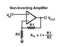
I understand now G=2.Easy picture. Reference datasheet for pin outs.
From the formula Av = 1 + R1 / R2.
then a R1 much more 'high may be used.
And of course R2 = R1.
Many thanks Torchwood
Av 2 shouldn't be needed with OPA627 - it is fairly well internally compensated, plenty of margin for unity gain operation
a series output R or L increases stability margins even further in case of driving the Capacitance of a cable
some also credit the series output parts + Zobel with cutting external RF/EMI entry
the OPA637 however does require a minimum gain to work reliably
a series output R or L increases stability margins even further in case of driving the Capacitance of a cable
some also credit the series output parts + Zobel with cutting external RF/EMI entry
the OPA637 however does require a minimum gain to work reliably
The regulator, power caps and bypass caps are very important here. It's too early to judge the performance of OPA627. As the buffer, I think OPA627 is a safe bet.
OPA627's
George found that the OPA627 sounded better in G=2 situation. Tried it and found it to be very nice. I did not try it as a G=1 in this situation. It is compensated as you mention.Av 2 shouldn't be needed with OPA627 - it is fairly well internally compensated, plenty of margin for unity gain operation
a series output R or L increases stability margins even further in case of driving the Capacitance of a cable
some also credit the series output parts + Zobel with cutting external RF/EMI entry
the OPA637 however does require a minimum gain to work reliably
- Home
- Source & Line
- Digital Line Level
- Using the AD844 as an I/V