2 mA DAC offset circuit
Hi Patrick, I would install the Pedja Rogic style offset circuit "if" the on board one doesn't zero. Here is how you know. Carefully probe the output pins on the dac with the black lead of the DMM on ground. A working null will measure 0 mV's. If your getting much beyond that it isn't working as designed. I am not all that familiar with your Arcam. They are not common here in the USA. 1.8 nF is used as a filter for a stable offset adjustments. Noise will disturb that adjustment. Can't comment on the LT1028. I'd take the signal clean without any network involvement. It may have unintended effects. 😉 If you had a dac to modify and not a CD player I'd tell you to dump the SAA7220 in favor of the NPC SM5814. It needs 2's complement MSB first, right justified data so to hard to use in a CD player unless it is a Sony with a TDA1541.Thanks Torchwood421 & George
well I consider taking this a step at a time, keeping changes to the PCB minimal for reversibility so far as it can go.
Now what comes after the IV I can wait with till later (and by the way I still have SAA7220 dig filter in there, BUT the Arcam Alpha5+ is not so stupidly build. It does not take the dirty clock out of SAA7220 and route it in to the DAC - instead a common clock split and individually buffered so TDA1541 gets a clean clock = one of LCaudio first clock designs)
BUT before the IV .. for simplest test just to get going
- could I use the bias circuit already existing as is (around the BC547)? -> else forced to use Rogics JFET biasing for starters = but reversibility for other opamps when swapping back to normal opamp IV?.
- do I need to put in 1.8nF from bias to ground for starters
- and can I leave the shunt network at the input (originally 1K but I further shunted it w 1uF + 2.2Ohm following suggestion by Rutgers wrt LT1028 IV)
/Patrick
OPA627's
I have parts on order and plan to build the OPA627 buffer this week and test it. I should be able to answer that question this weekend. BUF03's in general have a Class A sound. Rich with lots of musicality. Neutral? I don't know yet.Hi Torchwood & George
Thank you for the advice. Is the OPA 627 better sounding then Buf 03 George
Thanks
Yes, the BUF03 sounds a just a little bit raw/dirty in comparison, this can be heard especially in the top end with things like strings/cymbals/tamborines/brush work. The OPA627 stays very delicate and detailed.
Cheers George
Cheers George
Last edited:
Hi Guys
Thanks for the advice. George sound wise could also be due to capacitors that your using. I also notice that your using a common supply for both channels. From pass experience mono supplies for analog stage does make a fair bit of difference towards SQ.
Thanks again
Thanks for the advice. George sound wise could also be due to capacitors that your using. I also notice that your using a common supply for both channels. From pass experience mono supplies for analog stage does make a fair bit of difference towards SQ.
Thanks again
Capacitors
He doesn't like them in the sound path. His dac has a first order filter. When I tried that it sounded dirty too. I usually apply at least a 2nd or 3rd order passive filter. So my question is more does the BUF03 pass more of the products of conversion down stream as compared to the OPA627? Parts just showed up to build the OPA627 version buffer, so I will start chipping away at it. My DDNF + BUF03 with a 3rd order filter sounds like you are there. Will be interesting to see if that changes with the OPA627. 🙂Hi Guys
Thanks for the advice. George sound wise could also be due to capacitors that your using. I also notice that your using a common supply for both channels. From pass experience mono supplies for analog stage does make a fair bit of difference towards SQ.
Thanks again
Hi Torchwood
I know it's a matter of taste. Builded 2 dac & also own a couple. My fav used
to be Sonic frontier SFD ll . When I restarted diy this Nos dac thing caught my
curiosity so I bought the Aya Ds from Pedja. Been fiddling with it for some time.
What's really surprising is that it sound so so un digital , hard to explain & being
Nos there's just no digitis in it's play back at all. Now it makes me wonder if the
digital filters are creating more nasty's then good
SAA7220
NOS is a good work around for the really bad SAA7220 filter. I use the NPC SM5814. I am still able to use Pedja's developments to good effect. My current experiment the PCM1704 + DDNF + BUF03 is the most natural you are there experience to date. Some can get away with minimal filtering. It is really system dependent. George can take advantage of that. My system doesn't really sound good with just a 6 db / octave roll off. My speakers have rather large ribbon tweeters and so I am forced to use a passive 2nd order filter. Usually based around a Cinemag 600/600 transformer. In my experience the passive filter does less harm then putting it through some active op amp based filter. Those color the sound more then I like. Of course your experience may be different as no 2 systems in my experience are the same. 😀Hi Torchwood
I know it's a matter of taste. Builded 2 dac & also own a couple. My fav used
to be Sonic frontier SFD ll . When I restarted diy this Nos dac thing caught my
curiosity so I bought the Aya Ds from Pedja. Been fiddling with it for some time.
What's really surprising is that it sound so so un digital , hard to explain & being
Nos there's just no digitis in it's play back at all. Now it makes me wonder if the
digital filters are creating more nasty's then good
Last edited:
bias and pilot test w single AD844
well checked the existing bias now. The voltage divider resistors let approx 1½ mA through to the TDA1541A out. No measured offset at current opamp input (due to virtual ground). BUT approx -0.6V across the 1k feed back resistors. So looks like the opamp is supplying the remaining bias to the DAC.
So exchange the lower 4.7K voltage divider resistor w a 5K fine trimmer. Should always be able to bring me back where I were - but also be able to open up the current by lowering the value. Monitoring the feedback resistor voltage I am able to null it. Good. Sound now? only subtle change - if any thing bit leaner bas and slightly brighter top = wrong way !
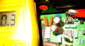
Now clipping the feedback resistor open & soldering 1.5K + 1nF across pin 3 and 5 of a single AD844 = drop in package. test the input offset now (as rtreimed previously w the LT1028 in place) = 0.3mV not too bad -> then fine trim to 0 (see attached photo of PCB)
Initial sound impression single AD844 = body in bas is back! = good. mid and top similar to LT1028 (maybe little more held back). SO resolution is similar but air and space a little less than LT1018 - also slightly less involving (bad!.. but ok I'll let it sit and burn in)
Next step make a 3 stack drop in package and see if that makes it better. If that works, see if can route pin 5 over to pins 6 (wrt drop in to the socket).
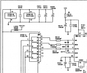
Question: what impedance can I load the TZ network with (>> RTZ = 1.5K or?) Arcams filter/buffer stage has a few K in a deemp stage before the filter/buffer opamp (see my first post schematic). Would like to reuse existing layout (maybe cutting/shorting something if needed)
cheers
/Patrick
Hi Patrick, I would install the Pedja Rogic style offset circuit "if" the on board one doesn't zero. Here is how you know. Carefully probe the output pins on the dac with the black lead of the DMM on ground. A working null will measure 0 mV's. If your getting much beyond that it isn't working as designed. .....
well checked the existing bias now. The voltage divider resistors let approx 1½ mA through to the TDA1541A out. No measured offset at current opamp input (due to virtual ground). BUT approx -0.6V across the 1k feed back resistors. So looks like the opamp is supplying the remaining bias to the DAC.
So exchange the lower 4.7K voltage divider resistor w a 5K fine trimmer. Should always be able to bring me back where I were - but also be able to open up the current by lowering the value. Monitoring the feedback resistor voltage I am able to null it. Good. Sound now? only subtle change - if any thing bit leaner bas and slightly brighter top = wrong way !
Now clipping the feedback resistor open & soldering 1.5K + 1nF across pin 3 and 5 of a single AD844 = drop in package. test the input offset now (as rtreimed previously w the LT1028 in place) = 0.3mV not too bad -> then fine trim to 0 (see attached photo of PCB)
Initial sound impression single AD844 = body in bas is back! = good. mid and top similar to LT1028 (maybe little more held back). SO resolution is similar but air and space a little less than LT1018 - also slightly less involving (bad!.. but ok I'll let it sit and burn in)
Next step make a 3 stack drop in package and see if that makes it better. If that works, see if can route pin 5 over to pins 6 (wrt drop in to the socket).
Question: what impedance can I load the TZ network with (>> RTZ = 1.5K or?) Arcams filter/buffer stage has a few K in a deemp stage before the filter/buffer opamp (see my first post schematic). Would like to reuse existing layout (maybe cutting/shorting something if needed)
cheers
/Patrick
Attachments
Single AD844
Hi Patrick, 1.5 mA current source... That is interesting. Yes. The feedback kind of messes the measurement up. In my experience a single AD844 isn't really an upgrade. Different for sure. TZ network value per Pedja is 1.5K Ohm for standard CD playback level. My PCM1704 dac uses 2.5K Ohm. The difference there is the 1704 outputs a current of only 0-1 mA. A TDA1541 and A will output 0-4 mA's. I am surprised your trying to use any of the original filter network. The easiest filter I know is a Edcor or Cinemag 600/600 transformer with 4n7 Polystyrene cap across the primary. Why not listen to the I/V and not the op amp filter? Anyway give it a try. My reference grade dac at this point is a dac in this configuration. DIR9001, SM5814, TDA1541, Pedja's discrete DDNF circuit with a BUF03 voltage buffer and a passive Cinemag based filter. Best 1541 based dac I have had in my system. 😀well checked the existing bias now. The voltage divider resistors let approx 1½ mA through to the TDA1541A out. No measured offset at current opamp input (due to virtual ground). BUT approx -0.6V across the 1k feed back resistors. So looks like the opamp is supplying the remaining bias to the DAC.
So exchange the lower 4.7K voltage divider resistor w a 5K fine trimmer. Should always be able to bring me back where I were - but also be able to open up the current by lowering the value. Monitoring the feedback resistor voltage I am able to null it. Good. Sound now? only subtle change - if any thing bit leaner bas and slightly brighter top = wrong way !
Now clipping the feedback resistor open & soldering 1.5K + 1nF across pin 3 and 5 of a single AD844 = drop in package. test the input offset now (as rtreimed previously w the LT1028 in place) = 0.3mV not too bad -> then fine trim to 0 (see attached photo of PCB)
Initial sound impression single AD844 = body in bas is back! = good. mid and top similar to LT1028 (maybe little more held back). SO resolution is similar but air and space a little less than LT1018 - also slightly less involving (bad!.. but ok I'll let it sit and burn in)
Next step make a 3 stack drop in package and see if that makes it better. If that works, see if can route pin 5 over to pins 6 (wrt drop in to the socket).
Question: what impedance can I load the TZ network with (>> RTZ = 1.5K or?) Arcams filter/buffer stage has a few K in a deemp stage before the filter/buffer opamp (see my first post schematic). Would like to reuse existing layout (maybe cutting/shorting something if needed)
cheers
/Patrick
Stacking AD844's...
Patrick, Be sure not to connect every lead together. We connect pins 2, 3, 4, 5 and 6's via 100 Ohm series resistors (if using internal buffers) pin 7's. You only need the null circuit on the bottom chip if used. 20K Ohm is the correct value for the trimmer. The data sheet has an error on that. The best results are had taking a high impedance buffer off the pin 5 TZ connection. OPA627 or BUF03. 🙂
Patrick, Be sure not to connect every lead together. We connect pins 2, 3, 4, 5 and 6's via 100 Ohm series resistors (if using internal buffers) pin 7's. You only need the null circuit on the bottom chip if used. 20K Ohm is the correct value for the trimmer. The data sheet has an error on that. The best results are had taking a high impedance buffer off the pin 5 TZ connection. OPA627 or BUF03. 🙂
Thanks Torchwood
well I try making minimal changes at the time so reversibility is still possible. If I like thinks really much I can step by step shave off excess components later
Yes am planning TZ output eventually, but both you and George use a buffer as loading the TZ network distorts the just cleanly created IV..so do you use a straight standard opamp buffer w near to inf input impedance? - but where is the practical 'pain limit' wrt loading the TZ netw : 15k 150k 1,5M? (so I know what to expect of 'shave off' operations needed..as existing output opamp netw essentially already is configured as a buffer (but w the filter caps around it). You trafo filter ideas is too much changes for now
AND I also though of taking the AD844 pin6 output directly, maybe on separate RCA's so I could swap via cables for A-B compare pin6 vs pin5 +ext buf
/Patrick
AD844's
Hi Patrick, Since the AD844 can be used with the internal buffer(s) you can connect a pin 6 output for comparison. While simultaneously having a buffer off pin 5. OK. The pin 5 TZ has a resistor, it is effectively the no negative feedback resistor. The cap across that resistor filters at a first order (6 db/octave). It also slows the input waveform from the dac by limiting bandwidth. As the TZ resistor sets the gain of the I/V stage... if you load it down you change the gain of the I/V. So my take is to stick with a known high input impedance op amp. These are usually JFET input. The OPA627 is a fine example as is the obsolete BUF03. The AD825 can also be used. So looking at the data sheets your looking for an input impedance greater then 100K Ohms. I'd prefer much higher then that say 1 Meg Ohm to a Gig Ohm. Just to limit gain changes. Avoid Bipolar input op amps they are simply to low an input impedance. My CD player modding days ended 8 years ago when my laser became defective on my old CDB650 Magnavox. It was highly upgraded. The standalone dac made sense at the time and I have never looked back. I do use a TASCAM pro CD recorder as a transport. It has a very good clock in it and a TEAC transport. I will never modify that. No point my 4 or 5 dac creations easily out perform it's internal AKM dac. 😉Thanks Torchwood
well I try making minimal changes at the time so reversibility is still possible. If I like thinks really much I can step by step shave off excess components later
Yes am planning TZ output eventually, but both you and George use a buffer as loading the TZ network distorts the just cleanly created IV..so do you use a straight standard opamp buffer w near to inf input impedance? - but where is the practical 'pain limit' wrt loading the TZ netw : 15k 150k 1,5M? (so I know what to expect of 'shave off' operations needed..as existing output opamp netw essentially already is configured as a buffer (but w the filter caps around it). You trafo filter ideas is too much changes for now
AND I also though of taking the AD844 pin6 output directly, maybe on separate RCA's so I could swap via cables for A-B compare pin6 vs pin5 +ext buf
/Patrick
Hi Tourchwood
Yes totally agree with your comment. My Sfd also contain a passive filter
prior to analog output. For now as far as Red Book play back is concern,
the nos tda is for me still the king especially in the way that Pedja has
implemented it. My speakers are ML Odyssey with some crossover mods which
is very very transparent. I can hear minute details changes that I make on
my system
Many thks again
Nice system!
Pedja did the DIY community a great service with his AYA dac and other DIY ideas. My system is very different maybe. My preamp is a Nelson Pass BA-3, it features 6 inputs and what sets it apart is both channels have dedicated Didden Super regulators and have independent power supplies. Like having 2 mono preamps in one enclosure. Configured stereo of course. The BA-3 has little in the way of filtering out of band stuff. I posted pictures at this forum. The amp is a "Class D Audio" amplifier made in California, I purchased the kit form so did the actual wiring with a tested amp module. 300 WPC... Speakers are Magnepan MG 2.5R's with reworked custom out board crossovers. My cousin owned them originally and changed the ribbon to a higher order roll off. This eliminated the maggie slam. So the crossovers are not in any way stock. The surprising thing is the system can rock. I even threw Metallica at it and it sounded great. Don't listen to much of that however it really shakes out any problems. Anyway that preamp is likely why I can't use a minimalist filter like George can. It just passes everything. 😱Hi Tourchwood
Yes totally agree with your comment. My Sfd also contain a passive filter
prior to analog output. For now as far as Red Book play back is concern,
the nos tda is for me still the king especially in the way that Pedja has
implemented it. My speakers are ML Odyssey with some crossover mods which
is very very transparent. I can hear minute details changes that I make on
my system
Many thks again
Hmmm looks like we're on the same wave lenght Torchwood. Lol
Me also been playing around with Hypex class D. Have both the
Ucd 180 & 400 but some how I prefer the sound of the Ucd 180
over the Ucd 400.
Cheers
Me also been playing around with Hypex class D. Have both the
Ucd 180 & 400 but some how I prefer the sound of the Ucd 180
over the Ucd 400.
Cheers
With the PCM1704K to 3x844 1st order filter (-3db @ 130khz) on TZ, then 1x 0pa627 x 2 gain (which also has on the FB network 1st order -3db at 130khz).
I get a miniscule 200uV if that (not mV) of noise on my output RCA's. No need for any sharper filter than that!
Yes I am filtering twice,, which would combined total, 2nd order at 130khz of -3db
Cheers George
I get a miniscule 200uV if that (not mV) of noise on my output RCA's. No need for any sharper filter than that!
Yes I am filtering twice,, which would combined total, 2nd order at 130khz of -3db
Cheers George
Last edited:
This weekend...
Hi George, Thanks for the clarification on the 2nd order filter. I built up the OPA627 stage although it is untested. It looks correct via continuity tests. Since I have the DDNF hooked up I will swap out buffers and see what my preference is. After that I can try the 3X AD844. I added pin 5 connections. So pretty much plug and play to a point. I have 2 buffer options OPA627 or BUF03. 200 uV's is miniscule. I can't even measure that low here. 🙂 Interestingly I have had the DDNF + BUF03 in the system for a week now. High frequencies are squeaky clean and crisp. Looks like my passive filter on the output is effective. abraxilito commented on my SM5814 thread that if the trebles are not clean then it is a reconstruction filter problem. Well... I don't know once I hear the OPA627 maybe I will notice if the BUF03 is really clean or not.With the PCM1704K to 3x844 1st order filter (-3db @ 130khz) on TZ, then 1x 0pa627 x 2 gain (which also has on the FB network 1st order -3db at 130khz).
I get a miniscule 200uV if that (not mV) of noise on my output RCA's. No need for any sharper filter than that!
Yes I am filtering twice,, which would combined total, 2nd order at 130khz of -3db
Cheers George
BUF03 in the system for a week now. High frequencies are squeaky clean and crisp. .
I also thought that, when I had the BUF03 in, and powerful like a freight train.
Only then when I heard the OPA627, it make me realize that the 03 was not as clean as I thought, and there's some sort of slight upper mid/highs distortion going on which stands to reason having no feedback like the 627 has.
And on the BUF03 data sheet there's no extensive distortion measurements done.
Cheers George
Attachments
'ratpack' a 3-stack?
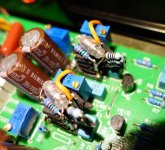
so just had little time yesterday to 'weld' a 3-some package together = full drop in on the opamp socket w all the support netw needed (only chnage to original is cutting feedback resistor open). See photo.. not beautiful, but compact
Had no time to adjust the trimmers etc as I was packing for a 1week trip to cottage - anyway had a quick listen - and compared to the single ad844 = yes more air and top refinement .. still bodyful bass.. so is in the direction of sound picture I want, good
Now your discussion wrt caps/active filter or not.. the ARcam 5+ does have 3-4 high quality PP caps w filter coef adjusted for the 4x OS .. so don't think they will bother in the audio band really (compared to my amps: Exposure VI/VII & super VIII, which are 'voiced' deliberately w lytics and tants in the signal path to get its sound..yes I like color and these amps make the feet stomp). ANyway I will try to wire the pin6 directly to the RCA and see/listen
AND later pin5 through the output chain of the Arcam (deemp+filter and all)..might remove the big coupling cap if dc-trim is effective (but not so critical as amplifiers as ac-coupled). The only low input impedance opamp in my collection is the LT1028, the other BJTs lt1357 and 1363 are 5-20Mohmish ..the FET a lot more..so for buffer/filter I will roll between these ones (OPA1611 might be the closet to the OPA627 you talk about)
Now the dig filter SAA 7220 being so bad? - well seems a lot to do w its current demand (->dirt on power lines) and non optimal 'hook up' in traditional designs. The arcam 5+ has a separate clock split to filter and dac - and the SAA 7220 output gets gated/reclocked before going into the tDA1541..so don't think it is all that bad. Yes I might clean the supply lines little more - might tune the impedance from reclock to TDA.. and read something about reclock DEM? (pin 16-17 on TDA1541, what ever that does?)..
but is this really worth the bother? (well as no higher quality drop in filter replacements boards are available for SAA7220, are there?)
/Patrick
Attachments
- Home
- Source & Line
- Digital Line Level
- Using the AD844 as an I/V