Hi,
I just noted, that You can´t simply replace voltage drive of a speaker by current drive, without taking additional measurements, like filtering (NIC-Filters e.g).
You do know what I do for a living?
The SNR of this thread is toxic.
Joe - can you please start a new thread for discussing your theoretical musing and leave this thread for those of us interested in AD844 implementation matters. Please dont reply to this request justifying your posts. Please just leave.
George and Joe: youve both damaged your standing and have only your own selves to blame. I will never purchase anything from you guys. I find it hard to believe two intelligent adults could disgrace themselves in such a puerile and public manner. Im ashamed for both of you.
The smart thing to do is // at pin 5 and use a single load resistor, that makes any output offset even smaller.
Jan
Yes, that's exactly how I've configured them. Summing the outputs via series resistors probably isn't required, but doesn't hurt either. The buffers all have gains close to = 1 and slight variations in vbe's might cause a slight variation in offset voltage, though admittedly I haven't taken measurements with a dvm.
Joe, your last pic is definitely NOT in series - two resistors, connected together at both ends - that the definition of parallel!
A voltage divider?? Both resistor have exactly the same voltage - they are connected on both sides! You really have to read up on this basic stuff!
Jan
I think he was trying to draw a parallel (pun not intended) between paralleled resistors across an ideal current source and series resistors on the output of an ideal voltage source (ie Norton vs Thevinin eq ccts.)
Btw, just catching up with the thread now, rather belatedly, having been away skiing in the alps.
Last edited:
Btw, just catching up with the thread now, rather belatedly, having been away skiing in the alps.
Seems you got the better deal then 😉
Jan
Seems you got the better deal then 😉
Jan
🙂 Seems as though the entire thread went downhill too.
Wow..
I laughed and laughed at that... Thanks! Back to the AD844 for sure....
This
I laughed and laughed at that... Thanks! Back to the AD844 for sure....
🙂 Seems as though the entire thread went downhill too.
So it's your fault Art.

So it's your fault Art.
Yeah!!! no more skiing for you David (Arty). And calling our ski field "Alps" common, our highest Kosciuszko mountain looks like an ant hill compared to real alps.
Cheers George
Last edited:
Yeah!!! no more skiing for you David (Arty). And calling our ski field "Alps" common, our highest Kosciuszko mountain looks like an ant hill compared to real alps.
Cheers George
Fwiw, they are called "the alps" - https://en.wikipedia.org/wiki/Australian_Alps
Besides, you're a surf man, George, not a snow man, so the alps as far as you're concerned is just a brand of potentiometer.

 Post deleted and possibly some more to come. Please do not bring previous thread wars to new threads.
Joe I have no beef with you as a person, I don't know you, and for all I know you might be the nicest person in the southern hemisphere.
But if you not seem to see the difference between series and // connection of resistors, I am allowed to point that out am I not?
If you call that persecution - what can I say?
BTW It is generally not a good idea here to comment on moderation in an open thread - just a hint...
Jan
But if you not seem to see the difference between series and // connection of resistors, I am allowed to point that out am I not?
If you call that persecution - what can I say?
BTW It is generally not a good idea here to comment on moderation in an open thread - just a hint...
Jan
Last edited:
commenting on moderation is not allowed under the rules, do it thru pm....or else your posting privilage will be taken away...FYI, Sydney is where Neville Thiele and Richard Small devised the Thiele-Small Parameters - that's a big deal to a lot of us.
That's funny, did you see my comment? Richard Small told me to my face that the cap across the DAC can't do anything useful.
Yes, the opamp based iv stage has +-12 (or +-15) available.
If you have that then I'm sure Abraxalito will be able to give you different values for his dac DC offset nulling circuit that I posted to make it operate with these + and - voltages as well.
Cheers George
Here is my humble attempt to go back to what this thread is all about:
I/V with AD844
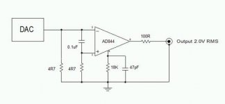
Recently I have implemented Joe`s Technique No2 to a Philips CD723 (DAC: TDA1545) with the following changes and additions:
Changed both 4R7 resistors to 10R and connected them to Uref (approx. 3.1V done by TL431 and fed to TDA1545 by 33K)) instead of GND.
Changed resistor at pin5 from 18K to 10K and capacitor from 47P to 100P.
Changed 0.1uF to 47nF
Changed the quartz (8.4672MHz) at SAA7378 to an external oscillator made up by a original PSX oscillator (67,7376MHz) and a 2:1 divider and pulled pin 13 (SELPLL) of SAA7378 to GND (cut and wire operation).
No changes to the power supply, maybe here`s another possibility to improve….
The maximum output level is a bit low (less than 1VRMS), so more gain is desired when your preamp has low gain (change resistor and cap at pin 5 to maybe 22K and 47P).
The result? Unbelievable that such a cheap (20€ on ebay) and simple player can perform like this, even better than using a pure passive I/V with the TDA1545. The passive solution sounds less refined to my ears.
For comparison I have used a modded OPPO BDP-95, which is no bad machine.
Lesson learned:
Try the things that clever and innovative people offer and create your own benefit and attitude. A solution maybe optimum for one guy but absolute crap for another man`s application. Be responsible, judge by yourself. Nobody else will know your requirements better than you by yourself.
I/V with AD844
Recently I have implemented Joe`s Technique No2 to a Philips CD723 (DAC: TDA1545) with the following changes and additions:
Changed both 4R7 resistors to 10R and connected them to Uref (approx. 3.1V done by TL431 and fed to TDA1545 by 33K)) instead of GND.
Changed resistor at pin5 from 18K to 10K and capacitor from 47P to 100P.
Changed 0.1uF to 47nF
Changed the quartz (8.4672MHz) at SAA7378 to an external oscillator made up by a original PSX oscillator (67,7376MHz) and a 2:1 divider and pulled pin 13 (SELPLL) of SAA7378 to GND (cut and wire operation).
No changes to the power supply, maybe here`s another possibility to improve….
The maximum output level is a bit low (less than 1VRMS), so more gain is desired when your preamp has low gain (change resistor and cap at pin 5 to maybe 22K and 47P).
The result? Unbelievable that such a cheap (20€ on ebay) and simple player can perform like this, even better than using a pure passive I/V with the TDA1545. The passive solution sounds less refined to my ears.
For comparison I have used a modded OPPO BDP-95, which is no bad machine.
Lesson learned:
Try the things that clever and innovative people offer and create your own benefit and attitude. A solution maybe optimum for one guy but absolute crap for another man`s application. Be responsible, judge by yourself. Nobody else will know your requirements better than you by yourself.
Attachments
question to joe r
i´m using this setup too and can you tell me please why pin 3 is not going straight to ground instead via a 4r7 resistor?
thanks
i´m using this setup too and can you tell me please why pin 3 is not going straight to ground instead via a 4r7 resistor?
thanks
Here is my humble attempt to go back to what this thread is all about:
I/V with AD844
Recently I have implemented Joe`s Technique No2 to a Philips CD723 (DAC: TDA1545) with the following changes and additions:
Changed both 4R7 resistors to 10R and connected them to Uref (approx. 3.1V done by TL431 and fed to TDA1545 by 33K)) instead of GND.
Changed resistor at pin5 from 18K to 10K and capacitor from 47P to 100P.
Changed 0.1uF to 47nF
Changed the quartz (8.4672MHz) at SAA7378 to an external oscillator made up by a original PSX oscillator (67,7376MHz) and a 2:1 divider and pulled pin 13 (SELPLL) of SAA7378 to GND (cut and wire operation).
No changes to the power supply, maybe here`s another possibility to improve….
The maximum output level is a bit low (less than 1VRMS), so more gain is desired when your preamp has low gain (change resistor and cap at pin 5 to maybe 22K and 47P).
The result? Unbelievable that such a cheap (20€ on ebay) and simple player can perform like this, even better than using a pure passive I/V with the TDA1545. The passive solution sounds less refined to my ears.
For comparison I have used a modded OPPO BDP-95, which is no bad machine.
Lesson learned:
Try the things that clever and innovative people offer and create your own benefit and attitude. A solution maybe optimum for one guy but absolute crap for another man`s application. Be responsible, judge by yourself. Nobody else will know your requirements better than you by yourself.
In Joe`s drawing both inputs are referrred to GND. When using this arrangement with a TDA1545 (or similar DAC) both inputs must be related to Uref = approx. 3.3V (DAC output has 3.3V DC) Otherwise you`ll have the DC-Voltage difference present at pins 2,3 which will then be amplified by 150...300 and the output will be at the supply rail. What you want is AC-signal-gain and as little DC offset as possible.
Hope this helps - I am not as good as other forum members in explaining electical behaviour....
Hope this helps - I am not as good as other forum members in explaining electical behaviour....

- Home
- Source & Line
- Digital Line Level
- Using the AD844 as an I/V