Yes, you are right. Without any other means the offset in my player was around -300mV. When you increase the gain, you may get more. You can use a coupling cap or some means of offset compensation to null it out. In my setup I could not null the output with the pins1,8 of the AD844 alone using the recommended offset arrangement as drawn in the datasheet. I connected an additional resistor (50K - 100K) from the plus rail to pin3/AD844. Then it was possible to null it out. If you change the gain of the stage you may need to adjust this resistor accordingly.
I could not null the output with the pins1,8 of the AD844 alone using the recommended offset arrangement as drawn in the datasheet. .
Pozo, maybe you missed it, but I believe the AD844 data sheet has a misprint re the offset nulling pot on pins 1 and 8.
It should be 20kohms not 20ohms, this may then work for you if it has the range. If not then Abraxalito's DC offset nulling circuit should.
And remember, the best sounding coupling cap is, no cap.
Cheers George
Thanks for the hint. I could not null the output with this measure alone trying pots from 50K to 10k. Adding a resistor from VCC to pin3 did the job of nulling the output. I have read about Abraxalito`s circuit but did not find the schematic. Leaving the coupling cap out.....to me there was no clear benefit...but I don`t want to go into that discussion....all have been said already.
Best regards
Best regards

Yes, you are right. Without any other means the offset in my player was around -300mV. When you increase the gain, you may get more. You can use a coupling cap or some means of offset compensation to null it out. In my setup I could not null the output with the pins1,8 of the AD844 alone using the recommended offset arrangement as drawn in the datasheet. I connected an additional resistor (50K - 100K) from the plus rail to pin3/AD844. Then it was possible to null it out. If you change the gain of the stage you may need to adjust this resistor accordingly.
Pozo, if all else fails, you can also insert a very small DC current from a supply through a large resistor into pin 5. For instance, if he offset is -100mV, with a 10k R at pin 5, you need offset current of 10uA. That would be a resistor of 1.5meg from pin 5 to V+ if V+ is 15V.
Jan
Offset
I pulled my DAC from service to confirm a few things. Wanted to see if I had ever used conventional feedback with the AD844. I didn't. In my TDA1541 D/A I am using Pedja's 2SK170 2 mA current source. I found no drift and both DAC outputs sat at 0.0 mV. In my build I have a triple stack with pin 6's all floating. Connected to nothing. I have a connection point wired up (bottom output) just not in use. In my build I go pin 5 (TZ) via 1 K resistors to the BUF03 buffer, Feedback resistor = 1.5 K. I look at it as a gate resistor. It adds nothing really considering the super high input impedance of the BUF03. For fun I probed the pin 6 connector and found -15 to -16 mV. Considering it is floating I am not concerned. Early on I did use this and had about -1.6 mV offsets. While I was in there I checked the power supplies and all is in specification. I decided to leave it alone as a reference. I have a new build in progress. WM8804 NPC SM5814 Parallel TDA1541A S1 Crown D/A (purchased in 1990). I am still working on the digital filter board and yet to finalize the I/V. Expect to have it on a bread board for testing in 2 weeks. Ultimately may try a balanced configuration. 😉Yes, you are right. Without any other means the offset in my player was around -300mV. When you increase the gain, you may get more. You can use a coupling cap or some means of offset compensation to null it out. In my setup I could not null the output with the pins1,8 of the AD844 alone using the recommended offset arrangement as drawn in the datasheet. I connected an additional resistor (50K - 100K) from the plus rail to pin3/AD844. Then it was possible to null it out. If you change the gain of the stage you may need to adjust this resistor accordingly.
In my setup I could not null the output with the pins1,8 of the AD844 alone using the recommended offset arrangement as drawn in the datasheet. I connected an additional resistor (50K - 100K) from the plus rail to pin3/AD844. Then it was possible to null it out. If you change the gain of the stage you may need to adjust this resistor accordingly.
Well done - exactly the right way to do it.
Try this, fit 0.33uF or 0.39uF across the top of 2 x 10R resistors.
Last edited:
Thanks for your recommendation. I`ll try it when I clean up my messy "birdsnest" setup.
Regards, Jürgen
Regards, Jürgen
Nests
 Enjoy it.
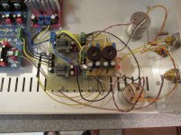
As long as it works....Here`s the nest, works better than it looks......
Enjoy it.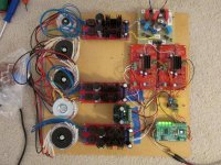
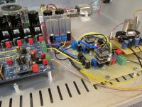
It's alive.... Tweaking it since last Thursday. Resistor I/V = 25 Ohms. SRPP ECC86/ 2SK170.... Results. Best DAC to date. So my question is with 0-8 mA output, would that seem to be to much for the AD844?
I think yes , as my PCM1704 does 1.2mA and while a single still sounded very nice with no nasties, the stacked was far superior to it.
PS: Not just the stacking of the I/V stage of the AD844, but the buffer stage as well getting stacked was also superior.
Cheers George
Last edited:
Parallel DAC
Hi George, I was thinking that as well. Since the AD844 is current starved by most accounts.... I'd bet it would be way to much for an AD844 or stack to cope with. So far the results are surprising. It pushes well beyond the Pedja discrete I/V in the Mark II although they are similar in some ways. More detail, more explosive dynamics while remaining musical. Did some Sine wave tests with a test disc and an oscilloscope and I see perfect analog Sine waves from 20 Hz to 20 Khz. Did not expect that....I think yes , as my PCM1704 does 1.2mA and while a single still sounded very nice with no nasties, the stacked was far superior to it.
PS: Not just the stacking of the I/V stage of the AD844, but the buffer stage as well getting stacked was also superior.
Cheers George
it definitely gives more air to the music... 😀Here`s the nest, works better than it looks......
Experiments
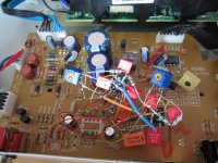
Hi George, It looks like it is going to be to much for an AD844. I put in my 7th order GIC filter. That has a pretty standard feedback type I/V. The LME49713 and another video opamp distorted badly. I could see pretty clean negative excursions however the positive signal is badly clipped. When you sum the 2 currents clearly the TDA1541's offset current also doubles. So at least for a "Parallel DAC" it seems the resistor I/V with SRPP is better at dealing with the high DC offset and higher current output. I mounted up my PCM1704's onto DIP adapters. I may start work on that next week. It seems most people feel that a balanced TDA1541 DAC isn't really worth while unless I have balanced equipment up stream. Sadly I don't. I should be able to try a double stack AD844 with the PCM1704's. 😉I think yes , as my PCM1704 does 1.2mA and while a single still sounded very nice with no nasties, the stacked was far superior to it.
PS: Not just the stacking of the I/V stage of the AD844, but the buffer stage as well getting stacked was also superior.
Cheers George
I should be able to try a double stack AD844 with the PCM1704's. 😉
I think you'll like the sound of it better, and you can dc couple it very easy as well.
Cheers George
PCM1704
How bad is the DC offset on a PCM1704?I think you'll like the sound of it better, and you can dc couple it very easy as well.
Cheers George
- Home
- Source & Line
- Digital Line Level
- Using the AD844 as an I/V