Yes a agree to some extent. But for a fixed frequency it is not that difficult to find a beat. And then look at the distortion when cancelleation is max.
Here is a measure ment with different cards same signal from REW. SPDIF is copied in output of card 1. Is used as input for card 2. (Cardd 2 has filtered output with distortion in bass. Else Card 1 and 2 is same type. ADAU and codec.Even with the same master-clocked signal, if the signal receivers (e.g. SPDIF receivers) and DAC chips are different, they introduce a different delay and the output signals will be out of phase and likely impossible to subtract properly - see https://www.wolframalpha.com/input?i=a+sin(x)+-+a+sin(x+++c) which is not zero.
They track very good.
The details is in the REW measurements enclosed.
At least a the measurement with cancelled fundamental trakcs the original distortion quite good.
But my understanding is that the ADC is not very much worse than the DAC wo filter at this DBFS level. The wo filter gets the w filter fundamental down about 30dBs at best.
Attachments
This is the cansellation of the fundamental.
Some phase or amlitude difference in the audioband of the two cards,Over 7 K is something going on? Might be positive dBFS at output
2 and 3 has same curve so 2 cant be seen

Some phase or amlitude difference in the audioband of the two cards,Over 7 K is something going on? Might be positive dBFS at output
2 and 3 has same curve so 2 cant be seen
Made a few stepped thd measurenments without filter.
ch 0 and 1 are balanced into ch a
ch 2 and 3 are balanced into ch b
ch a and b are balanced into single ended ADC
ch b can be muted or inverted.
To me it looks like the 4 channels behave very consistent.
ch 0 and 1 are balanced into ch a
ch 2 and 3 are balanced into ch b
ch a and b are balanced into single ended ADC
ch b can be muted or inverted.
To me it looks like the 4 channels behave very consistent.
Attachments
Wonder if I could use inverted X^3 ADAU sigma studio module to get 3.rd harmonic down.
To be able to verify it ch 0,1,2 and 3 must generate "the same" 3.rd harmonic. Probbably I will need to be able to adust the phase on the X^3 also.
I could then both get my clean source for cancellation and a clean signal.
I will ponder that. But don't have time to verify if it is possible or wrong theory this weekend.
Thats strange.
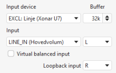
If I do not select EXCL input, second harmonic varies on the same input channel. I change output channel on adau. No changing of cable or input to measurement ADC.
If it is EXCL the second harmonic is much more stable. (And I get less second harmonic when using diff) Some time for fault seeking that I am never getting back🙄

1 is ch0 non EXCL input
2 is ch1 non EXCL input
3 is ch0 EXCL input
4 is ch1 EXCL input

If I do not select EXCL input, second harmonic varies on the same input channel. I change output channel on adau. No changing of cable or input to measurement ADC.
If it is EXCL the second harmonic is much more stable. (And I get less second harmonic when using diff) Some time for fault seeking that I am never getting back🙄
1 is ch0 non EXCL input
2 is ch1 non EXCL input
3 is ch0 EXCL input
4 is ch1 EXCL input
Attachments
Last edited:
It actually functions to generate the cansellation on one channel and use that cansellation of 3.rd harmonic on another channel.
It is of course best result on the channel where it is hand callibrated (0 and 1), but nice midle value on other channel (2 and 3). 3. harmonic sine is always sent on channel 0 and 1

It is of course best result on the channel where it is hand callibrated (0 and 1), but nice midle value on other channel (2 and 3). 3. harmonic sine is always sent on channel 0 and 1
If not perfect result is needed one channel could then be used for finding calibration values and the other for actual measurement.
So calibration could be found at same time as previous measurement.
So calibration could be found at same time as previous measurement.
ADAU sigma studio model used. Value for 3. harmonic calibration value found by handtuning volumecontrol and delay on x^3 leg. Then do the right muting and unmuting

15 minutes I'll never get back.... ;-)
Torgeirs, what is the assumption behind all this? Do you hope to get a more precise measurement of the harmonics out of the ADC when you suppress the fundamental, by amplifying the difference signal (with the suppressed fundamental) to be further away from the noise floor of the ADC? If that is the plan, then where is that additional amplification coming from, and how do you know that amplifier doesn't introduce noise & distortion?
Without some more background on what you are trying to achieve (measure SNR for DAC1 using an ADC and a DAC2, with SNR(DAC2) > SNR(DAC1) > SNR(ADC) ?), and how, this thread seems more your way of note keeping for your tests than a forum discussion. A basic sketch that includes signal levels would help. The Sigma DSP graph is not really the measurement, but just a part of the signal preparation, right?
I'm looking at ways to get better measurement values of harmonics than the DAC or ADC has in its spec,
Then I need to introduce more elements. In this experiment series it is differential amps and more DACS.
First I had some misconceptions, mostly that the phase of harmonics is not stable. They are quite stable.
So by using known wisdom like harmonics are a*x^n series and that phofman has been able to suppress harmonics by using filter and number crunching, I want to investigate if this can be done in a even cheaper or simpler way. (If you dont have to go down to sub -130 dB)
Now i had the delight of getting a 3.rd harmonic down to these measurements and I am quite pleased
Last edited:
Post #2 shows the experimental hardware setup
It would be better for me if I had better DACS and ADC to demontstrate, but I don't. The setup is what I've got.
The SPDIF source and measurement ADC is ASUS U7 USB card. Very good mid priced card 10 years ago
It would be better for me if I had better DACS and ADC to demontstrate, but I don't. The setup is what I've got.
The SPDIF source and measurement ADC is ASUS U7 USB card. Very good mid priced card 10 years ago
Last edited:
The whole journey is a moving target. So measure and adjust the direction as my mantra.
But I try to stick to the ADAU card with the 8 ch codec card the 3 difference amps and the ASUS card,
In some posts I have also used an unmodified codec card with quite a lot of distortion
But I try to stick to the ADAU card with the 8 ch codec card the 3 difference amps and the ASUS card,
In some posts I have also used an unmodified codec card with quite a lot of distortion
The frequency sweep of the -3dB setup. Digital cansellation of 3.rd harmonic.
Just like the 3.rd harmonic has a comb filter😍

Just like the 3.rd harmonic has a comb filter😍
Maybe I'm cancelling also ADC distortion here, but that has phofman showed that can be separated with some filter and number crunching.

Post #2 is detail pictures of wiring, Torgeirs. Can you produce a sketch of the overall setup, ideally with approximate signal levels between the devices? Otherwise you are just talking to yourself. Which, you know, can be fine ;-)
- Home
- Design & Build
- Equipment & Tools
- Using audio line receiver for measuring stereo DAC with cheap ADC