Mark,
I think you have a point on the ferrite beads. Recently I saw couple of articles and perhaps for the assembly of new boards would replace the beads with 0 ohm resistors.
The purpose of the reclock is to align all signals with the masterclock edge. So for that reason it is preffed to use one IC where all 8 flip-flops have very similar timings because they are on the same die. This is why I said earlier that reclocking on FPGAs may be (not always) pointless.
I think you have a point on the ferrite beads. Recently I saw couple of articles and perhaps for the assembly of new boards would replace the beads with 0 ohm resistors.
Although it it true, it is not a major factor in this case.The ground bounce you will have is from different signals switching at different times and all drawing current through the same IC ground bond wire. Well known problem if not using single (1G) flip-flop ICs.
The purpose of the reclock is to align all signals with the masterclock edge. So for that reason it is preffed to use one IC where all 8 flip-flops have very similar timings because they are on the same die. This is why I said earlier that reclocking on FPGAs may be (not always) pointless.
Yes, I follow the thread. And by the way, I believe it can be used together with York with no issues 🙂Thread on the whole clocking and reclocking thing starts at: https://www.diyaudio.com/community/threads/general-purpose-dac-clock-board.413001/ Somewhere in there I had a reclocker board I got from Andrea Mori. I started to suspect there might be problems so started doing some experiments to see. Turned out there were problems so I designed a new reclocker that works and sounds better according to everyone who has started trying it, or else trying derivative designs. Link to my reclocker is in first thread post linked above.
All articles about issues with ferrite beads I've seen related are related to possible problems with digital gates. Clocks or clock buffers are not digital gates but closer to analogue circuits.
Chapter 5 in this recent report from TI gives good guidelines about the use of ferrite beads:
https://www.ti.com/lit/pdf/sprabv2
One thing to keep in mind is that ferrite beads on clocks or clock buffer supplies can only impact the clock signal itself so that possible impact should be visible in measurements. However nothing is seen even at levels far below any human hearing threshold. The highly touted supposedly SOTA Andrea Mori's clocks so no signs of issues even though they use plenty of ferrites.
So instead of buying into unsubstantiated claims from subjective sighted listening evaluations without proper controls IMO it is better to ask for evidence that is verifiable. So far no such evidence has surfaced.
Last edited:
I would strongly suggest to try it and listen. ITD localization scrambling with semi-random noise is not so easy to measure with a spectrum analyzer, but its quite easy for humans to hear on a good system.
As some people try this experiment for themselves they can form their own opinions as to what works or what doesn't.
Moreover, I find attempts to dissuade people from doing their own experiments and forming their own opinions as something very difficult to understand. "Warning people to conform with standardization even when its wrong," is what it looks like to me.
It seems you are the one repeatedly warning people when they don't conform to your ideas just as in this thread. I find that very difficult to understand.Moreover, I find attempts to dissuade people from doing their own experiments and forming their own opinions as something very difficult to understand. "Warning people to conform with standardization even when its wrong," is what it looks like to me.
As you don't have any measurements how about something easier:
- Can you show us detailed images of the boards you used for comparisons with/without ferrites. Based on those images we can assess if your implementation is according to TI's guidelines?
- Do you have an image of the test setup showing the boards and how the switching was done in the comparison test?
- Proper AB testing should rely on short-term memory and near-instantaneous switching in listening comparisons as stated in this ITU document: https://www.itu.int/dms_pubrec/itu-r/rec/bs/R-REC-BS.1116-3-201502-I!!PDF-E.pdf. How did you accomplish near-instantaneous switching in your comparison test?
Let add something related to what I have said about my thoughts on the ferrite beads on the reclock board.So instead of buying into unsubstantiated claims from subjective sighted listening evaluations without proper controls IMO it is better to ask for evidence that is verifiable. So far no such evidence has surfaced.
The oscillators have dedicated LDO so I am not concerned about the noise, the configuration of LDO + caps (0805 close to LDO and 0402 close to each oscillator) are totally fine in my opinion. There are no other high frequency aggressors in the system, masterclock would be the main harmonic.
The only reason why I put the beads is to isolate oscillators from each other. However, since they never work together, it does not matter.
The regulator PSRR is good enough in the HF region, so it would really make sense not do add impedance between LDO and the oscillator.
P.S. I literally work in company that produces all kinds of timing devices 🙂
Let me just add that not everyone agrees with TI on everything. For example:

Above sourced from a book published by: https://speedingedge.com/
Regarding the work I did on this subject, it done several years ago using the no longer supported Circuit Studio to design the PCB on an old computer that is no longer in use. I have no interest in repeating the work all over again just to settle an internet forum argument. I would suggest that people do their own experiments and form their own opinions. Leaving pads for ferrites in order to do a comparison is not necessarily a bad idea.
Some additional information attached, and some other info may be found at: https://purifi-audio.com/blog/tech-notes-1/this-thing-we-have-about-hysteresis-distortion-3
Attachments
Last edited:
Once again you are confusing digital power delivery networks with clock or clock buffer supplies which are analog.
Quote from TI's guidelines:
"Ferrite beads (especially forming Pi filters) are recommended for analog and PLL power connections."
Quote from TI's guidelines:
"Ferrite beads (especially forming Pi filters) are recommended for analog and PLL power connections."
Nobody asked for your prior work but details about your supposed listening tests where you claim to have heard a difference. But since you have nothing to show we can leave it at that and agree that your claims are based only on opinions.Regarding the work I did on this subject, it done several years ago ...
Look, PJotr25 made is own clock board without ferrites and with both clocks running at once. The output spectrum he measured looks like this:

Again, no ferrites and both Crystek clocks running at once. Ferrites are not needed. Period.
https://www.diyaudio.com/community/...e-dac-clock-board.413001/page-12#post-7804266
BTW, an experiment can be done Crystek, or even with Iancanada S-cut crystal clocks. Unplug the clock not in use from the board and there is no change in the sound, not even through electrostatic speakers. Other people have done the same one-or-two-clocks-installed experiment in other countries. They get exactly the same result, no difference with one or two clocks running at the same time (and no ferrites needed).
The only difference in sound that was found was in another experiment which showed that sound is much better if the clock board is designed my way. The person in that case had two identical dacs with only his design version of the clock board being different. The one that sounded better was the one I helped advise on.
Last edited:
I agree that ferrite beads are not needed to separate two clocks but other than that you don't seem to understand why ferrites are used in analog circuits. Just read the TI guidelines.Again, no ferrites and both Crystek clocks running at once. Ferrites are not needed. Period.
And if the sound difference was found in another experiment not done by you I suggest not using that as a reference unless you have sufficient details of the setup and test procedures. It is just hearsay as it stands.
Sorry to keep dealing with fallout of the above mistaken claims in this thread, but this is where the claims were posted.One thing to keep in mind is that ferrite beads on clocks or clock buffer supplies can only impact the clock signal itself so that possible impact should be visible in measurements. However nothing is seen even at levels far below any human hearing threshold.
By now people who like to rely on spectral analysis and audibility thresholds for single tones should know better than to make claims as to what is audible with noise or noise-like signals as they appear in a frequency magnitude spectrum (spectral analysis).
In the time domain, noise-like signals can have varying frequency content. The relative phases of those frequencies will determine the sound, amplitude, and or audibility of the signal in the time domain. Clock jitter is often a noise-like signal, and in that case its time domain intensity is completely unknowable from looking at spectral analysis plots. I have tried to explain why that is over and over again, but it doesn't seem to stop people who just don't get it from making claims based on very small or non-existent changes in noise floor magnitude. In fact there doesn't need to be any change at all in spectral noise floor amplitude for the time domain waveform to go from a very, very low volume level, to an ear-splitting approximation of an infinite amplitude impulse.
For people who still don't understand about noise and spectral analysis, they might be wise not to make unsupported claims about thresholds of audibility for noise-like signals based on published PSS HD partials audibility research. Its completely inapplicable.
Last edited:
Maybe open a new thread for your discussion? Very informative and useful content to post in its own thread, rather than on a Vendor's product thread. Just a suggestion.
Who said anything about spectral analysis. You seem to have a fixation on ASR. I said the impact is measurable down to levels far below audibility. Besides how would you know how high the noise impact is without measuring it?By now people who like to rely on spectral analysis and audibility thresholds for single tones should know better than to make claims as to what is audible with noise or noise-like signals as they appear in a frequency magnitude spectrum (spectral analysis).
As you have nothing to show you just keep on speculating.
Here are the basics for measuring clock jitter in time domain:
https://www.edn.com/basic-jitter-measurements-using-an-oscilloscope/
Last edited:
can we pls stop this bickering, just open your own thread on this subject pls - i get notifications for this thread and like to see york vendor updates not the discussions
An update on the hardware:
1. I've got new batch of Pico v2 version so it back in stock:

2. I've also ordered batch of nano (or mini 🙂 ) version. It is still not fully released yet, I would need to work on documentation. So in next couple of weeks it will be available in the tindie store as well.
3. New version of reclock board
Based on feedback for the first version, I've added more footprints for oscillators:

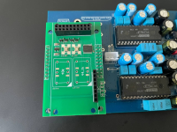
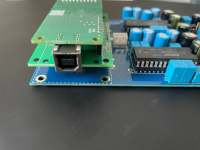
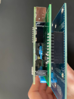
Another update is that York is flipped now so that total heigth of DAC-Reclock-York is not that high:

And there is enough space for any clocks:

1. I've got new batch of Pico v2 version so it back in stock:
2. I've also ordered batch of nano (or mini 🙂 ) version. It is still not fully released yet, I would need to work on documentation. So in next couple of weeks it will be available in the tindie store as well.
3. New version of reclock board
Based on feedback for the first version, I've added more footprints for oscillators:

Another update is that York is flipped now so that total heigth of DAC-Reclock-York is not that high:

And there is enough space for any clocks:

I think this device are just what I'm looking for. Can anyone confirm that I can do as following:
Connect this device as an bridge between:
HTPC running Ubunto on USB
Feed two Zoudio amps
 with I2S 48kHz 24-bit?
https://zoudio.com/product/aio438/
Connect this device as an bridge between:
HTPC running Ubunto on USB
Feed two Zoudio amps
https://zoudio.com/product/aio438/
Eclipsevl,An update on the hardware:
1. I've got new batch of Pico v2 version so it back in stock:
View attachment 1415131
2. I've also ordered batch of nano (or mini 🙂 ) version. It is still not fully released yet, I would need to work on documentation. So in next couple of weeks it will be available in the tindie store as well.
3. New version of reclock board
Based on feedback for the first version, I've added more footprints for oscillators:
View attachment 1415132
Another update is that York is flipped now so that total heigth of DAC-Reclock-York is not that high:
View attachment 1415133
And there is enough space for any clocks:
View attachment 1415134
Does v2 work with in multichannel 6ch.mode?
Oh my god, my apologies for the delay.Eclipsevl,
Does v2 work with in multichannel 6ch.mode?
Not this one. There will be another one with FPGA.
Updates on the project:
1. I launched a very basic webpage finally.
It took just one evening to make it so a long overdue. But now the docs, config tool and some updates of the firmware will be available in one place. Welcome!
http://york.eclipsevl.org
2. The config tool now really checks the firmware version:

3. In a new config tool it is now possible to change not only name and vid/pid but also manufacturer and serial ID string of the descriptor.

Also it is possible to specify the terminal type. It changes how the interface is seen in the os:

On the firmware updates:
Biggest one is the fix of device enumeration with iPhones. Now York is iPhone compatible.
1. I launched a very basic webpage finally.
It took just one evening to make it so a long overdue. But now the docs, config tool and some updates of the firmware will be available in one place. Welcome!
http://york.eclipsevl.org
2. The config tool now really checks the firmware version:
3. In a new config tool it is now possible to change not only name and vid/pid but also manufacturer and serial ID string of the descriptor.
Also it is possible to specify the terminal type. It changes how the interface is seen in the os:
On the firmware updates:
Biggest one is the fix of device enumeration with iPhones. Now York is iPhone compatible.
- Home
- Vendor's Bazaar
- USB UAC2+HID Multichannel input/output interface York