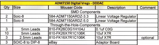
ADM7150 DIY Vreg's
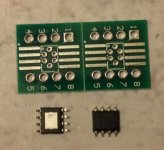
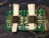
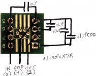
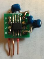
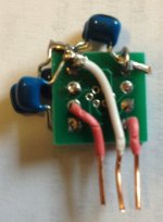
I built two 3.3V ADM7150 Vreg's and one 5V ADM7150 Vreg from parts costing about the same as one SPM Belleson or Tent Shunt voltage regulator http://www.analog.com/media/en/technical-documentation/data-sheets/ADM7150.pdf. Below is the BOM for this set of three Vregs. This is one of the easier adaptor board diy projects; however, the resulting Vregs look lumpy and uneven. See pictures below. The component layout must be made with the available Main and DAC boards mounting space kept in mind. Because there is a heat dissipation pad on the bottom of the ADM7150 chip, I bent the legs downward and used a strip of paper to keep the grounded pad from touching the SOIC adaptor board. These Vregs do not get more than warm to the touch in these low current DAC applications.
IMO these Vregs sound at least as good as the Belleson’s, however, I upgraded the digital bypass caps at the same time. The ADM7150 is used in some diyinhk power supplies. The power supply provided for the highly regarded Pulsar DAC clock uses the ADM7150. http://www.pulsarclock.com/ds/Pulsar_Power.pdf I just found out that Acko sells LM78XX compatible Vregs using the ADM7150 for $35usd https://sites.google.com/site/ackodac/home.
I will mail a set of 3 SOIC adaptor boards to the first two persons wanting to built a set for $6 including shipping and PayPal. I would like to know what others think of these.
Attachments
Looks good Ross. Are you ending up with something similar spec wise to these?
http://tekdevice.com/chapter2/index.php?route=product/product&path=25&product_id=87
I have a couple of those in my dac mainboard and s03 and they seem fairly well specced for the digital circuits.
I'd want something capable of sinking current too for the analogue side though, so I suspect a shunt reg will still be king there.
James
The one from Ross has a much better ripple rejection but delivers a little less current.
Ed
The one from Ross has a much better ripple rejection but delivers a little less current.
Ed
Cool, thanks 🙂 sounds like a good option for the digital stuff 🙂James
The one from Ross has a much better ripple rejection but delivers a little less current.
Ed
Maybe a nice candidate for another small run of custom pcbs?
Inexpensive DIY ADM7150 Vreg's
The DIY ADM7150 Vreg was offered as an inexpensive way to replace the standard LF33/LF50 Vregs witht better sounding Vregs for the DAC and Main Board I2S handling chips. For those who can easily afford it - I recommend buying the many available finished digital Voltage regulators.
I have no idea how how my adaptor board ADM7150 Vreg specs out or ultimately how good it sounds compared to other digital Vregs. I am counting on others to help determine this. More fun for those who want to keep trying new tweaks.
I'm glad the the 2SK208-O tested best because I sent out about 250 of them for the CCS GB.
Ross
Hi Ross,
I fully agreed with you... It is not sense to design and build a dedicated board for the AMD7150 when there are already available and very well done from Acko or others as you mention already. There is nothing to invent here and we can just do something worse. I have some of the Acko regulators in the hands and they are really well done.
Regards,
Enrico
AMD7150 diy regs
HiEnrico,
Ross says, you can d.i.y. build THREE regs for the same price you pay for ONE Acko/Diyihk reg.....something most of us will like.
Ed
Hi Ross,
I fully agreed with you... It is not sense to design and build a dedicated board for the AMD7150 when there are already available and very well done from Acko or others as you mention already. There is nothing to invent here and we can just do something worse. I have some of the Acko regulators in the hands and they are really well done.
Regards,
Enrico
HiEnrico,
Ross says, you can d.i.y. build THREE regs for the same price you pay for ONE Acko/Diyihk reg.....something most of us will like.
Ed
Last edited:
HiEnrico,
Ross says, you can d.i.y. build THREE regs for the same price you pay for ONE Acko/Diyihk reg.....
Ed
Hi Ed,
Yes, it is exactly what Ross says BUT using the small adaptor board.
I was referring to the idea to design a dedicate PCB and run another GB. I don't think that we can reach any best result at a best price.
Regards,
Enrico
½ clock delay circuit power sup
Hi. What do you guys use to feed that board (other than Belleson)? In the meantime, I'll take the 5V from the Twist.Pear Placid (old version) I have for the WaveIO. Thanks. Pierre
Hi. What do you guys use to feed that board (other than Belleson)? In the meantime, I'll take the 5V from the Twist.Pear Placid (old version) I have for the WaveIO. Thanks. Pierre
½ clock delay circuit power sup
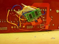
The 1/2 clock board gets its power from the red Main Board which should have 5V. You do NOT need an additional power supply. See picture at bottom of: http://www.diyaudio.com/forums/digi...e-board-pcm1794-nos-dddac-42.html#post4239418 The large white and red wires are soldered to the Main Board.
Hi. What do you guys use to feed that board (other than Belleson)? In the meantime, I'll take the 5V from the Twist.Pear Placid (old version) I have for the WaveIO. Thanks. Pierre - crazyfrog
The 1/2 clock board gets its power from the red Main Board which should have 5V. You do NOT need an additional power supply. See picture at bottom of: http://www.diyaudio.com/forums/digi...e-board-pcm1794-nos-dddac-42.html#post4239418 The large white and red wires are soldered to the Main Board.
Yes, thanks. Sorry if I didn't make myself clear. I meant better than that. Thought Placid could be better.
The 1/2 clock board gets its power from the red Main Board which should have 5V. You do NOT need an additional power supply. See picture at bottom of: http://www.diyaudio.com/forums/digi...e-board-pcm1794-nos-dddac-42.html#post4239418 The large white and red wires are soldered to the Main Board.
Better digital Vreg
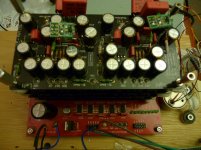
It might be, but the Belleson and several other digital Vregs that would plug directly into the Main Board or fitted on the DAC board are very good. These applications draw very little current on the red main board. It is my understanding that, regarding digital Vregs, closer to use points is better. I would never recommend a remotely located digital Voltage regulator for the DDDAC main board or digital PCM1794 circuits. I have a high current Belleson plugged directly into the 5V terminal block on the WaveIO board. I am very pleased with the sound quality.
Thought Placid could be better.- crazyfrog
It might be, but the Belleson and several other digital Vregs that would plug directly into the Main Board or fitted on the DAC board are very good. These applications draw very little current on the red main board. It is my understanding that, regarding digital Vregs, closer to use points is better. I would never recommend a remotely located digital Voltage regulator for the DDDAC main board or digital PCM1794 circuits. I have a high current Belleson plugged directly into the 5V terminal block on the WaveIO board. I am very pleased with the sound quality.
I have a high current Belleson plugged directly into the 5V terminal block on the WaveIO board. I am very pleased with the sound quality.
A friend and I both use this arrangement but with New Class D regs and we are both very pleased with the SQ
Hi Enrico, Ross,
Finally I had the time to implement the CCS for pin 20 and the 1/2 clock delay PCB. The PCB's makes the work easy. The pin 20 upgrade was for me immediately, but a bit bright. After 2 week 24/7 the brightness has gone.
Yesterday I implemented the 1/2 clock delay. I cut the traces on the mainboard, while the treads from the mainboard to the deck are all still in place. Is this correct?
I did not got instant improvement in sound, only till sofar the top deck (out of 4) I replaced the 1k resistor for 100 Ohm. May be that is the reason?
Paul
Attachments
i2s resistors must be less than 100r for half clock cycle delay
1 k is far too much and will sound wrong
1 k is far too much and will sound wrong
pz1
If you got music the 1/2 clock wiring is correct. The main board Vreg should be 5V. The 1/2 clock delay chips add a negligible amount of current load. Ditto nige2000 for replacing all the 1K with 100 ohms on ALL DAC boards.
Did you install CCS boards on all 4 DAC boards?
If you got music the 1/2 clock wiring is correct. The main board Vreg should be 5V. The 1/2 clock delay chips add a negligible amount of current load. Ditto nige2000 for replacing all the 1K with 100 ohms on ALL DAC boards.
Did you install CCS boards on all 4 DAC boards?
pz1
If you got music the 1/2 clock wiring is correct. The main board Vreg should be 5V. The 1/2 clock delay chips add a negligible amount of current load. Ditto nige2000 for replacing all the 1K with 100 ohms on ALL DAC boards.
Did you install CCS boards on all 4 DAC boards?
all boards need to be identical
like tug o war

the team needs to pull together
or it just doesnt work right🙂
- Home
- Source & Line
- Digital Line Level
- Upgraded Single Board PCM1794 NOS DDDAC