I got my parts from Ross today! 🙂
Just seeing the tiny parts and the hand written specs and everything organised nicely gives a little insight into how much work was involved.
Thanks again Ross, I imagine you never want to measure another jfet every again.....
So am I the first guy to have both lots of bits?
I'm also one of the only guys to already have a buffer stage up and running, as I have one of the prototypes, so although I'll swap to this new one with the nice board, I have a few other things to sort out first.
One thing I would say, having done a fair bit of surface mount soldering lately, is that I would highly recommend the use of Solder Paste (not SolderING paste, which tends to just be flux) as that means you can apply the solder, place the parts exactly where you want them using tweezers, then melt the solder paste.
something like this: SN62 619D 4 86%, 35G INC PLUNGER - QUALITEK - SOLDER PASTE, 619D, SN62, 35GM | CPC
I've only discovered it very recently, but it makes working with SMD massively easier and cuts down on time, problems and swearing
Hi James,
We both are jumping from a thread to another 🙂
I am happy to know that you have received your parts and your PCBs.
I am anyway curious to have your feedback about the board design so I hope to hear from you soon...
Thanks for the tips about the solder paste. Really useful for who still is not confident with the SMD (like I think everybody was, me first, the first time we are requested to manage those minuscules parts).
Regards,
Enrico
Hi Enrico and Ross!
Got Ross' parts today too. Nicely packed and numbered! What a tremendous job. Thanks!
I will have to wait for Ross' leading hands putting the buffer together though.
Ed
Got Ross' parts today too. Nicely packed and numbered! What a tremendous job. Thanks!
I will have to wait for Ross' leading hands putting the buffer together though.
Ed
Got my GB boards
I received my boards and will populate and test a buffer and pair of CCS boards. I will then post detailed instructions in this thread. Boards look great!
I'm glad the first wave of buffer & CCS SMD parts are beginning to arrive. The JFETS are in paper fold-up pouches which can be most easily removed with an X-acto knife or razor blade. Several months ago I tried taping the JFETS to a piece of paper, but they became sticky and wouldn't always let go from the SMD mounting tweezers.
parts
got the parts today! thanks a lot, ross!
i hope that the pcbs will arrive soon as well, so i can the assemble the buffer/ccs modules.
regards
got the parts today! thanks a lot, ross!
i hope that the pcbs will arrive soon as well, so i can the assemble the buffer/ccs modules.
regards
I got my parts from Ross yesterday. Many, many thanks!
Was to busy with other things to order other parts, so my build will have to wait for some more time. And I also will better wait for Ross instructions.
Torsten
Was to busy with other things to order other parts, so my build will have to wait for some more time. And I also will better wait for Ross instructions.
Torsten
CCS Board Assembly Instructions
The board is so small (10mm x 15mm) that it is easier to leave the boards connected to each other so that they don’t move around so much while soldering components. I succeeded on my first try at soldering and testing a pair of CCS boards with matched SMD resistors. They both measured within +/- 0.001ma of 0.400ma when I was done. The number written on the JFET pouch is the total resistance needed for the 2SK208 to operate at 0.40ma. The paper pouch is easily opened with a razor blade or X-acto knife.
1. Solder all the SMD components including the 2SK208, fixed resistor, and pot area SMD resistor if you ordered the parts kit with matching resistor values. SMD tweezers are a must! SMD techniques are recommended, but not absolutely necessary if you are careful. NOTE: I used a small soldering tip with Wonder solder. The soldering pencil heat was the same as for soldering through-the-hole components. I put a small amount of solder on the gate pad for the JFET and on one pad for each of the SMD resisters. Next I held each SMD component in place and touched the hot tip to the pad leg junction until the solder melted – usually within 1 second. Next I soldered the other leads/ends by putting the solder between the component and the hot tip and pushed through the solder until there was solder flow – again usually less than 1 sec. You may want to resolder the first solder joints if they don't look good enough. I am 67 and don’t have the steadiest hands or great eyesight and limited SMD experience – so it should be “a piece of cake” for you guys to succeed at this. I didn’t use a magnifying glass, but it would help.
2. TEST: Measure the fixed resistor by putting an ohm meter across the two TP points. The 2SK208 and it’s solder connections can be tested be putting a meter in the diode test mode and putting the red/pos probe on the JFET gate and touching the black meter lead to the pin 20 hole and then to the right TP hole. You should get readings between 0.2 and 0.8.
3. If everything appears ok then install a multi-turn 500 ohm pot if matching resistors were not used. Depending on the available space and orientation of your DAC installation, the pot can be installed on either side of the board and aimed upward or outward from the CCS board. Pots can be obtained with the adjusting screw at the top or side of the pot. 1K or 2K pots can be used if that is what you have on hand. You can use a smaller value pot as long as it is larger than the total resistance number minus the fixed resistor value.
4. Install wire leads from the Pin 20 and GND holes long enough for battery or breadboard testing if desired. They can be shortened later.
5. Adjust the Pot until the resistance from the right TP to GND equals the desired total resistance. Your CCS board is done.
6. TEST: A 1.5V battery can be used to test the CCS before installing it in your DAC. The packet I sent you also has a label for the voltage you should get from volt meter leads across the 2 TP holes. The voltage should be at least 95% of the voltage you should be getting at 2.4V from pin 20; after all, it is a CCS device.
7. If the DAC has already been operating with the 6K resistor at pin 20, then measure the DC voltage at the Rload resistors for future reference. Shorten the CCS leads. Replace the 6K resistor with the CCS board. If the ground end of the 6K resistor is inaccessible because of the components around it, run a wire from any ground plane point on each CCS board to the Rload common points on the DAC board. You may want to rotate the CCS board about 90 degrees to the side. This is what I had to do.
8. Power up the DAC. You should be getting a voltage near what you measured with the 6K resistor in place. A difference within +/-5% should be fine. If your DAC has an Rload resistance of 133ohms/board you should measure within +/-0.1V of 2.7V at Rload A-pos, A-neg, B-pos, and B-neg to Rload common. If you have a CCS with a pot you can adjust to get closer to 2.7V if you wish. Rload resistors at 135 ohms will read a little higher at about 2.74V.
Much has been posted about the positive sq changes from the CCS. No one has reported going back to the 6K resistors. The sound may be bright at times but this should go away after about 300 hours of music play time. The increased dynamics and detail will remain.
Attachments

Hi Ross,
The parts arrived today. Thanks very much for the huge amount of work you put in. The instructions you are going to post will be more than welcome. This will be my first attempt at soldering surface mount parts, so I will need all the help I can get.
Jan
The parts arrived today. Thanks very much for the huge amount of work you put in. The instructions you are going to post will be more than welcome. This will be my first attempt at soldering surface mount parts, so I will need all the help I can get.
Jan
Hi dwjames,
What is the best way to melt the soldering paste? How do you do this?
This would be a neater looking and more even soldering job instead of globby looking like my SMD projects.
Carlsor
What is the best way to melt the soldering paste? How do you do this?
This would be a neater looking and more even soldering job instead of globby looking like my SMD projects.
Carlsor
Hi Ross,
By richly using flux, and correct positioning of the tiny parts, there should be no problem useing a normal soldering iron and led/tin solder. Cleaning afterwards will make the work look really pro-like!
Ed
By richly using flux, and correct positioning of the tiny parts, there should be no problem useing a normal soldering iron and led/tin solder. Cleaning afterwards will make the work look really pro-like!
Ed
Well the best way is a hot air solder station, but with solder paste it seems you can do a perfectly acceptable job with a normal small soldering iron. As far as I can gather, solder paste is basically very finely ground solder dust mixed with a small amount of flux paste.Hi dwjames,
What is the best way to melt the soldering paste? How do you do this?
This would be a neater looking and more even soldering job instead of globby looking like my SMD projects.
Carlsor
I like the fact that the part doesn't move during soldering if you use paste. Previously I was tinning the pads with normal solder, holding the parts roughly in place and melting the solder whilst pushing down, but I always found they tended to shift about in a way that wasn't helpful and led to mistakes. Paste is much easier to do a neat and functional job first time. I just wish I knew that about 6 months ago....
My parts arrived today and a HUGE thanks Ross and a huge task you did for us all.
Now the fun begins
Now the fun begins
My approach to SMD soldering is putting a bit of solder on one PCB pad first (usually a corner pin for ICs, and the more suitable one for anything else). Then I grab the component holding the tweezers in my left hand. Holding soldering iron in my right hand I remelt the solder previously deposited on the one pad and I place the component into the molten solder while aligning it properly. Then I solder in a standard way all the remaing pads. With ICs I normally solder the opposite corner pin as the 2nd and then the rest.
In case if the pins have a very small pitch and the solder spreads to a neighbouring pins and creates a short circuit, then I use a solder wick to remove the excess solder. At the end I check all the neighbouring pins for short circuit using a multimeter with very fine measuring tips.
It's also advisable to use a fine tip on the soldering iron as well as a fine solder wire (normally <0.4mm in diameter works well).
This approach works very well for me and I hope it'll help someone here as well.
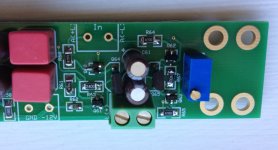
GB Buffer Board Assembled
I assembled my first GB Buffer board and it WORKS! I replaced an earlier broken-in prototype buffer board with this new buffer board and it sounds good, except for that "new parts" sound. A new break-in time period begins. When it approaches about 300 hours of music play time and sounds so bad I want to throw it against the wall - I will know that I am within a day of musical Nirvana. There will be stretches of pleasing and improving sq up until then.
The Cinemags should sound like they put their "big boy pants" on. No longer polite and thin sounding when driven by a single board DAC. If you haven't ordered your through-the-hole parts yet, I suggest that you add a pair of inexpensive 150pf WIMA FKP2 film caps to the order and install these on the outputs of the Cinemags to also break-in. Afterwards you can decide if you like how these affect the sound. IMO these make the musical details sound more real.
Attached are some pictures. I will post the Assembly, testing, and adjustment procedure shortly.
Attachments

Nice job Ross and Enrico. With this board and the smd components it looks really nice and neat 🙂
Have you got a link or BOM handy for the rest of the buffer components please? I had a quick look but couldn't find it.
Thanks again,
James
Have you got a link or BOM handy for the rest of the buffer components please? I had a quick look but couldn't find it.
Thanks again,
James
I assembled my first GB Buffer board and it WORKS! I replaced an earlier broken-in prototype buffer board with this new buffer board and it sounds good, except for that "new parts" sound. A new break-in time period begins. When it approaches about 300 hours of music play time and sounds so bad I want to throw it against the wall - I will know that I am within a day of musical Nirvana. There will be stretches of pleasing and improving sq up until then.
The Cinemags should sound like they put their "big boy pants" on. No longer polite and thin sounding when driven by a single board DAC. If you haven't ordered your through-the-hole parts yet, I suggest that you add a pair of inexpensive 150pf WIMA FKP2 film caps to the order and install these on the outputs of the Cinemags to also break-in. Afterwards you can decide if you like how these affect the sound. IMO these make the musical details sound more real.
Attached are some pictures. I will post the Assembly, testing, and adjustment procedure shortly.
Hi carlsors,
Glad to know that the board is working 🙂
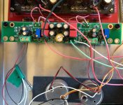
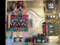
You did a great job showing everybody the board installed. Thanks!
I am really curious to know which breadboard you have between the dac and the waveio? It is a kind of reclock?
Best Regards,
Enrico
WaveIO Reclocker
Enrico,
Yes, this is a simple reclocker with just a 100mhz Crystek and two Potato PO74G74A D-flip flop chips. I posted this at http://www.diyaudio.com/forums/digi...pcm1794-waveio-usb-input-346.html#post4120369 including a picture. I think I have a picture of the schematic somewhere if you are interested.
There are no instructions on what components to put on the Acko S03 board to work best with the WaveIO so I am staying with the breadboard for awhile. The change in sq is very small - unlike the CCS boards which result in a big change in the liveliness and detail of sound.
Thanks 🙂Hi James,
You can found the complete BOM at page 11 post 105 from carlsors.
Regards,
Enrico
- Home
- Source & Line
- Digital Line Level
- Upgraded Single Board PCM1794 NOS DDDAC