Hi Torsten,
Thanks, I miss to reply you 🙂
I hope you are happy with the boards.
Nobody else received them?
Regards,
Enrico
not yet
GB SMD Parts Status
Testing and matching of ALL JFETs for CCS and Buffers is done. Parts mailed to all CCS GB only persons. I started mailing the rest of the SMD parts packages and plan to get them all out by the middle of next week.
By the way, I haven't received my GB boards yet. When I get them I will immediately assemble a buffer board and a pair of CCS boards. From this I will post detailed instructions on assembly, testing, and adjustments.
I would appreciate receiving a PM when you get the SMD parts.
Carlsor
An externally hosted image should be here but it was not working when we last tested it.
Just arrived, thanks Enrico! 🙂
Mine arrived yesterday as well, I'll watch you build yours first ;-)
I will as soon I get my parts... we are in the same ship 🙂
Regards,
Enrico
My boards arrived today and great quality. Thank you very much for doing this and a great GB! 🙂
My boards arrived today and great quality. Thank you very much for doing this and a great GB! 🙂
Thanks SimonJ for let me know

I see that many peoples will be busy in the week end 😀
Regards,
Enrico
Thanks SimonJ for let me know
I see that many peoples will be busy in the week end 😀
Regards,
Enrico
Can't build mine yet as no parts but I am not in a rush. My new DDDAC kit has just been sent too and will use these with that kit 😀
My boards have just arrived too Enrico, thank you.
Great! Thanks for let me know 🙂
Regards,
Enrico
Dear Enrico,
My pcb's arrived this afternoon, loks very nice.
Thanks very much for your GB and effort.
Hoping to get some pictures how exactly you connected your 1/2 clock delay to the red MB.
Best,
Paul
My pcb's arrived this afternoon, loks very nice.
Thanks very much for your GB and effort.
Hoping to get some pictures how exactly you connected your 1/2 clock delay to the red MB.
Best,
Paul
Dear Enrico,
My pcb's arrived this afternoon, loks very nice.
Thanks very much for your GB and effort.
Hoping to get some pictures how exactly you connected your 1/2 clock delay to the red MB.
Best,
Paul
Hi Paul,
Happy to know that you guys are receiving the boards 🙂
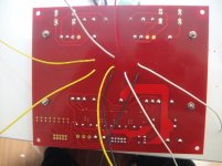
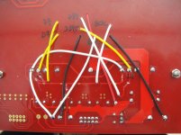
Attached are few pictures that should help you to understand the connections of the half clock delay.
To build mine I do the following steps:
- Allocate the 1/2 clock board in the top of the mother board (better with some paper tape) and mark the 9 small holes.
- Marked in the mother boards the holes as per 1/2 clock PCB (like D7, D7.5, D39 etc...)
- Soldered the 9 piece of wires into the 1/2 clock board (better with different colors).
- Inserted the cables in the holes and fixed the 1/2 board with a small bi-adesive tape.
- Revert the mother boards and make the connection as per schematic (in the pictures you can see clearly the traces that have to be cut and where the wires should be soldered)
I hope this can help you but let me know...
Regards,
Enrico
Attachments

- Home
- Source & Line
- Digital Line Level
- Upgraded Single Board PCM1794 NOS DDDAC