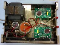
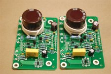
I took an old Dynaco Stereo 120 Power amp, and made some PCB's to retrofit LM3886s. I've attached a picture of the first completed version. I haven't listened to it yet, but the quick measurements so far:
*a bit more than 60 Watts into 8 Ohms before it clips
*harmonics of 1 kHz better than 80 dB below the fundamental below clipping
*3 dB frequencies of 10 Hz and 100 kHz
*about 1.1 Vrms input for full power output
The insides look a bit nicer than they used to, I think...Hopefully I can set it up for some listening in the near future. (picture is just a quick snap from my cell phone camera).
Attachments
I would use a "real" heat-sink for those LM's. I do not think what you are using as a heat-sink will be enough to cool down those chips ( unless you do not push them) The LM3886 can get really hot if they do not have an adequate heat-sink. Just my thoughts!!!😉
Heat management
The heat management of the ST120 was to me it's biggest failing, worse than the crossover distortion it would produce at volumes lower than a clock radio. I never listened at volumes that low anyway, but after a 3 hour choir rehearsal at probably 10 W minimum/ channel, mine melted the solder on the snap-in output cap (not the original dynaco with the holes in the tabs) and produced a 12" fireball from vaporized solder when the solid core wire pulled away. The junior choir was very impressed with the fireworks. After a needed break, the rehearsal finished on the ST70.
My original output ST120 with the DJoffe quiet bias increase pcb, will get hotter than bathwater at the transistor flanges after 4 hours idling or 1 V output service. I'm satisfied with the sound, so rather than change the output transistors, I put "Mouse Ears" on it. Two 3" fans salvaged from PC switcher power supplies blow through the cover on the two output transistor mounting flanges. They are screwed to a steel channel sitting under the amp, and are powered by a 9VDC wall transformer separate from the St120 power supply. As the whole hi-fi is on a power strip, this is not an operational problem. At 12 hours, the output flanges are cool to the touch.
I have plenty of surplus heat sinks but haven't figured a way to cram them in and still put the cover on. PA amps use fans pretty universally, anyway. On into the 40th year of this tough beast. It is now amplifying the output of my HDTV tuner on PBS network music shows.
Last edited:
Are you using a unipolar PSU and output capacitors there? Different. Useful if there's a DC fault though as it will save your speakers!
unipolar supply and speaker cap
Yes...the original supply is regulated 72 Volts, so I'm using that single supply and a 3300 uF output capacitor
Yes...the original supply is regulated 72 Volts, so I'm using that single supply and a 3300 uF output capacitor
Thermal Data...enough heatsinks?
I thought lanchile's caveat about heatsink size was worth looking into. My conclusion is that for any kind of "normal" listening, recycling the Dynaco heatsinks should be adequate. Here's the data I took:
I drove one channel into 8 Ohms (didn't have two power loads), and found the following temperature rise data for the driven channel:
Ambient temperature is 25 C.
Temperatures measured with a thermocouple on the case of the driven LM3886.
These measurements (except #4) were made with the perforated top removed:
1. Temperature measured with a thermocouple on the case of the LM3886.
Power up the amp, with no signal, case temperature of LM3886 stabilizes at 39 C (e.g. human body temperature).
2. If we rate the amp at 60 watts into 8 Ohms, then the old FTC 1/3 power pre-conditioning test calls for pushing 20 Watts into 8 Ohms, or an output voltage of 12.65 volts RMS. The case temperature was 100 C in this condition.
3. Calculations show that on a 72 Volt supply, 16 V RMS is about the worst-case internal dissipation. In that case, we have worst case case Temperature of 108 C.
4. Same test conditions, but with the top in place, case temperature increases to 112 C.
Some thoughts...This is probably a test much rougher than any normal listening. Even in this case, we're beneath the limits assuming 25 C ambient.
Thermal resistance from junction to case is 1 C/W. Worst-case internal dissipation is about 32 W, meaning the junction temperature will be 32 C above the case temperature. That says with the given heat sinks, driving 32 Watts continuous into 8 Ohms (a worst-case condition), makes the junction temperature around 140 C. The part is rated to Tj=150 C, with an instantaneous SOA temperature of 250 C, per note 9 on the data sheet.
So...for normal listening...heatsinks probably adequate...for high ambient temperatures, or very compressed music at very loud levels, you might want to use finned heat sinks, as lanchile recommends.
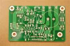
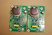
Close up of the bare PCB
Here's a close up of the bare PCB that I used to make "modern" amplifier modules to replace the original ones in the Stereo 120.
For reference, the other picture is the PCB side of one of the original modules.
I'll try to upload a stuffed board picture in a day or so.
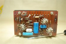
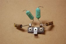
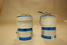
OK...I added a third and a fourth picture...the old zobel networks and the output caps with the wound 'round inductors...just because it almost looks like art!
Here's a close up of the bare PCB that I used to make "modern" amplifier modules to replace the original ones in the Stereo 120.
For reference, the other picture is the PCB side of one of the original modules.
I'll try to upload a stuffed board picture in a day or so.
OK...I added a third and a fourth picture...the old zobel networks and the output caps with the wound 'round inductors...just because it almost looks like art!
Attachments
Last edited:

Schematics on the way
I'll try to post the schematic in the next day or so...It's done in a kind of heavy duty system that isn't appropriate for posting...I'll try to make a clean pdf to post.
I'll try to post the schematic in the next day or so...It's done in a kind of heavy duty system that isn't appropriate for posting...I'll try to make a clean pdf to post.
Looking for a Power Switch
The Stereo 120 original power switch is a neon-lamp illuminated crystal rocker switch. It mounts with mounting screws on 1.375" centers (my measurement is rougher than that). Closest switch I found is by NKK, but it's a bit too wide, and a bit too far between the mounting holes, I think. The rocker needs to pass thru a rectangular hole about 1" tall and 0.4" wide.
(warning-measurements based on ruler, not calipers).
So...does anyone have any idea where I can find such switches? It looks like a similar switch was used on the PAT-4 Preamp?
Thanks...
I'm using this rocker switch from electronicsurplus.com 3-614 - 16AMP 125V/ 10AMP 250VAC ROCKER SW, BLK a carling non-lighted. It will push through a 3/8" x 1" hole with spring tabs on the back. For best results you can make a bezel out of sheet brass or steel with a die grinder wheel on a mandrel and a drill motor with clearance bits for 4-40 screws. #32 or #31. You'll need needle files and a triangle file to clean up the hole. Use safety glasses.
Not really a machinist...
How cheesy does it come out if you just push that switch into the existing hole?
Do you need to widen the hole to make that switch fit?
Is the hole too big, so the switch swims around?
How cheesy does it come out if you just push that switch into the existing hole?
Do you need to widen the hole to make that switch fit?
Is the hole too big, so the switch swims around?
Last edited:
My ST120 switch still works, so having a spare is a luxury, not a requirement. Bought these switches for my 3 channel organ amp project. (which is going to be 3 ST120 channels of some sort, might be your chip schematic, or the original. Have the O.T's output caps and heat sinks for the original). For the ST120 if you cut the spring ears back a little bit with diagonal pliers, it might just fit. The switch body itself looks like a perfect fit going on your measurment (I haven't taken mine out). Cramming the ears through top & bottom from the outside may require a little metal filing top & bottom. There is also a little strut top & bottom that looks like it needs to be cut & filed off. They are $1.50 each, but surplus charges $10 shipping anywhere in US, so look around, see what else they have. I got 100 crimp terminals for my tractors & cars, some 1n5344 diodes for regulated power supplies for op amp modules, etc.
If you have a drill motor, 3" cutoff wheels are $1.50, mandrels are $3, diamond dust hole enlarger bits are $12 a set (harbor freight), needle file sets about $1.50, (flea market), real nicholson triangle files about $8. (hardware store), safety glasses $2. Not a lot of money for tooling. Non-listed sources are mcmaster.com.
If you have a drill motor, 3" cutoff wheels are $1.50, mandrels are $3, diamond dust hole enlarger bits are $12 a set (harbor freight), needle file sets about $1.50, (flea market), real nicholson triangle files about $8. (hardware store), safety glasses $2. Not a lot of money for tooling. Non-listed sources are mcmaster.com.
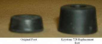
Found the Feet
The rubber (plastic?) feet on the Stereo 120 degrade after 40 years or so.
I found that Keystone part number 728 (available from Mouser as Mouser's part number 534-728) is a pretty nice replacement. It's a bit taller, but the same hardware still fits. Enclosed picture shows the comparison, with the two original feet on the outside, and the new Keystone foot in the middle. (focus isn't great because I got a bit closer than I should have).
Attachments
Power Switch
I found this web site in Germany that may be a source of Dynaco parts...
Dynaco Classic Audio Spareparts
You'll have to use Google Translate to read some of the pages (unless you speak more German than I do)...I have emailed them, and am awaiting a response on a power switch.
I found this web site in Germany that may be a source of Dynaco parts...
Dynaco Classic Audio Spareparts
You'll have to use Google Translate to read some of the pages (unless you speak more German than I do)...I have emailed them, and am awaiting a response on a power switch.
Thanks for the work here D!
I'm thinking of doing the same to reuse the Dyna chassis instead of rebuilding PC15s.
It's that easy to use a single-ended P/S with these chips? I'd sure like to reuse the P/S (after recapping PC14).
I'm thinking of doing the same to reuse the Dyna chassis instead of rebuilding PC15s.
It's that easy to use a single-ended P/S with these chips? I'd sure like to reuse the P/S (after recapping PC14).
An Update Kit for the Dynaco Stereo 120
Gentlemen,
It's finally ready for prime time...the update of the classic first transistorized power amp is available. Take a look at:
Update My Dynaco
for more details, plus some useful papers that analyze the circuits in detail.
All the best...
djoffe
Gentlemen,
It's finally ready for prime time...the update of the classic first transistorized power amp is available. Take a look at:
Update My Dynaco
for more details, plus some useful papers that analyze the circuits in detail.
All the best...
djoffe
The website looks really good djoffe.
I built one of the prototypes of this kit, and I've been very pleased with the sound from the refreshed Dynaco. The instructions are great, and it's really a pretty simple kit to put together.
I'll post a picture of my amp when I have some time.
I built one of the prototypes of this kit, and I've been very pleased with the sound from the refreshed Dynaco. The instructions are great, and it's really a pretty simple kit to put together.
I'll post a picture of my amp when I have some time.
- Status
- Not open for further replies.
- Home
- Amplifiers
- Solid State
- Updating the Dynaco Stereo 120