I'm actually using NTE60 O.T. on one side with RCA TO5 driver transistors (original) and on the other side NTE181 OT with TO220 NTE49 & 50 driver transistors. I can't hear any difference between sides. I did install the capacitance part of the "TIP mod" to slow down slew rates on PC15, but didn't install actual TIP transistors.Hi,
That is why I used the 2N3442G that is twice the working voltage of the power supply. If you try to make the amplifier to reach the clipping area the 2N3055 will short burning the diodes, the 100ohm resistor and the Q3 & Q6.
The 2N3442 I just downloaded from datasheetcatalog.com (ON semi) shows Ft of 80 khz minimum. The NTE60 has Ft of 2 mhz minimum with Vceo of 140. NTE181 is no longer online. I think the faster Ft might be a good idea. Somebody on this forum did sims of a 70 W british amp with 2n3772 Original Equipment, 2n3055, TIP3055 on same RC background, and the sim sound was better each time the output transistors got faster. I like the way my up to date (1992 on O.t') ST120 sounds.
You might look at MJ15015 instead of 2N3442, after you install the driver slowdown caps of the TIP mod. I got a dozen for $1.60 ea from newark.com last year in case the NTE O.T's go. They have a nice fast Ft (800 Khz), 120 Vceo, defined safe operating area all the way up to 120V. See if you like the sound better. While you have them off, put individual TO3 finned heatsinks above the mica washer on the flange. It can't hurt anything. You have to bend the tabs down to clear the cover, but still.
Hi,
I like the MJ15015 because the working voltage is 120 volts. The output power can be increase until reach the clipping without shorting it. This is one of the final test I do to my rebuilt. If you do that to the 2N3055 it will go and burned.
Thank you I will try next time.
I like the MJ15015 because the working voltage is 120 volts. The output power can be increase until reach the clipping without shorting it. This is one of the final test I do to my rebuilt. If you do that to the 2N3055 it will go and burned.
Thank you I will try next time.
Hi,
I checked the Hfe on the 3 transistors 2N3055, 2N3442 and the MJ15015 found they have the same value of 20-70. I am going to buy a pair and try the clipping test. See what happened when they reach the clipping.
I checked the Hfe on the 3 transistors 2N3055, 2N3442 and the MJ15015 found they have the same value of 20-70. I am going to buy a pair and try the clipping test. See what happened when they reach the clipping.
Assembly Video
Here's a youtube link for the assembly process of updating a Dynaco Stereo 120:
YouTube - Updating a Stereo 120 with the UpdateMyDynaco kit
Here's a youtube link for the assembly process of updating a Dynaco Stereo 120:
YouTube - Updating a Stereo 120 with the UpdateMyDynaco kit
Power Supply Troubleshooting Guide Update
I've updated the power supply circuit description and FAQS with two new FAQs about diagnosing start up problems. Here's the link:
Update My Dynaco
Then click on the link "Power Supply Circuit Description and FAQS". It should be in the middle of your screen.
I've updated the power supply circuit description and FAQS with two new FAQs about diagnosing start up problems. Here's the link:
Update My Dynaco
Then click on the link "Power Supply Circuit Description and FAQS". It should be in the middle of your screen.
Some measurements, old and new
Here's a link to measurements of the original amp, and the updated amp, concentrating on low output levels (0.5 Watts and 6.25 mW), looking at the residual spectrum. It shows clearly the crossover distortion harmonics of the original design.
Update My Dynaco
Here's a link to measurements of the original amp, and the updated amp, concentrating on low output levels (0.5 Watts and 6.25 mW), looking at the residual spectrum. It shows clearly the crossover distortion harmonics of the original design.
Update My Dynaco
I liked your original solution of a bias controller better than the chip amp: http://www.diyaudio.com/forums/solid-state/156627-dynaco-stereo-120-can-beautiful.html I'm using mine 18 hours/day with the mickey mouse ear fan addition. It sounds better than the ST70 with new output tubes, at 1V pp in my living room. Did you ever actually build and test one? Since you are not selling bias mod dual TO3 PC15's I'm slogging on laying a mask out by hand with a black marker- My computer with Ubuntu won't run free Windows layout programs. The copy shop promises to make 2:1 reductions in xerography using any paper I bring in. It's either this or the MR8 capacitor coupled amp that uses the exotic $11 fets that aren't stocked in the USA. When I play my organ I play the bass channel at 30 watts for minutes at a time. JS Bach was power mad in his youth.
Thanks for the kind words about the mod. I've been thinking about making an official PCB for it, but I don't think there would be enough demand.
More Measurements
I did some more measurements, comparing the stock stereo 120 and the UpdateMyDynaco version. You can see the new measurements at:
Update My Dynaco
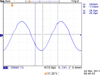
I'll also post here an interesting waveform from the stock unit, a 20 kHz "sine wave" at the output, about 350 mV peak-peak into 8 Ohms. See the visible crossover notch.
I did some more measurements, comparing the stock stereo 120 and the UpdateMyDynaco version. You can see the new measurements at:
Update My Dynaco
I'll also post here an interesting waveform from the stock unit, a 20 kHz "sine wave" at the output, about 350 mV peak-peak into 8 Ohms. See the visible crossover notch.
Attachments
Comparisons of Old and New
I've revised the web site to show some AP Plots of distortion for the original and updated version.
Take a look:
Update My Dynaco
I've revised the web site to show some AP Plots of distortion for the original and updated version.
Take a look:
Update My Dynaco
Revised Power Supply circuit description...New FAQs
I've added a few new FAQs to the power supply circuit description.
http://www.updatemydynaco.com/documents/PowerSupplyCircuitDescriptionRev9.pdf
I've added a few new FAQs to the power supply circuit description.
http://www.updatemydynaco.com/documents/PowerSupplyCircuitDescriptionRev9.pdf
Historically Interesting Power Amplifier
Here's a link to some historically interesting power amplifiers...
Update My Dynaco
The scans of the old articles are a bit on the big side, but they're pretty high res.
100 Watt Transformer Coupled Delco Amp
JBL's Classic T Amp
Ampzilla
Here's a link to some historically interesting power amplifiers...
Update My Dynaco
The scans of the old articles are a bit on the big side, but they're pretty high res.
100 Watt Transformer Coupled Delco Amp
JBL's Classic T Amp
Ampzilla
Another Historic Amp
Updated the scans to be a bit better to read, added a scan of an article from 1962, by General Electric...A direct coupled amp that looks a lot like the stuff we're still doing...
Update My Dynaco
Updated the scans to be a bit better to read, added a scan of an article from 1962, by General Electric...A direct coupled amp that looks a lot like the stuff we're still doing...
Update My Dynaco
More Historic Power Amplifiers
The link at the bottom will get you to hi-res scans of classic articles on historic power amplifiers, namely:
# Ampzilla review from Audio Magazine
# SWTPC's Universal Tiger Power Amplifier
# Marshall Leach's Low Tim Audio Power Amplifier
# The first commercial Class G Amplifier
Update My Dynaco
Note: since they are pretty high res scans, download might take a little time, depending upon your internet connection speed. Note that there are a couple of links for some historic tube amp articles.
Thank you for putting up the information on your website - the only thing I do NOT like about the LM3886 is the protection kicking in. Funnily enough, out of curiousity, I breadboarded the original ST120 layout, trying complementary 3055/2955 outputs. Imagine my surprise when the quasi version actually sounded pretty good (!), and the complementary version sounded horrible (spiky distortion).
I do like the Delco 100w design - now if I could only get a transformer...
Bart Locanthi's circuit has the very great advantage of graceful overload capability, but is somewhat harsh-sounding; I suspect that all the H3 and other odd-order distortions are magnified by the cascaded differential topology.
Car Radios Used to be Class A
Added another historic schematic...Delco car radio output stage from 1962...Class A!
Update My Dynaco
Added another historic schematic...Delco car radio output stage from 1962...Class A!
Update My Dynaco
Transistor Design Used to Be Really Mysterious
Transistor design was pretty mysterious in 1957. Lou Garner and GE
recommend pots everywhere to do transistor design in this column from Popular Electronics.
Sorry, the file is big, it may take a bit to download, but there's lots of interesting stuff here in the ads surrounding the article, from a 1957 copy of Popular Electronics...I think the ads are about as interesting as the article!
Here's the link:
Update My Dynaco
Calculating Power Dissipation in Power Amps
Nothing startling, but maybe an easy to understand tutorial on calculating power dissipation in power amps.
Here's the link:
Update My Dynaco
then click on
Calculating Power Amplifier Dissipation
Nothing startling, but maybe an easy to understand tutorial on calculating power dissipation in power amps.
Here's the link:
Update My Dynaco
then click on
Calculating Power Amplifier Dissipation
The change to metal tab version...POWER
I recently changed the UpdateMyDynaco design to the metal tab version of the LM3886. I had considered it when I made the original design, and shied away owing to concerns about the disposition of the ground currents. It's the kind of thing that could theoretically be a problem, but the actuality is somewhat implementation dependent. Being conservative at that time, I chose the insulated tab version.
Subsequently, one of the forum members, looking at this thread, had suggested the change to the metal tab version. His comment prompted me to consider it again. It took a while for me to get around to making the change, and making the measurements. They have shown that there's no issue with the change the way the design is configured and wired.
The interesting results, from an LM3886 design retrofit into a Dynaco Stereo 70 chassis and power supply:
Power supply: 76.7 Volts, regulated (nominal 72, but this one was a bit high).
One channel driven.
Clipping into 8 Ohm load around 75 Watts.
Clipping into 4 Ohm load around 130 Watts.
It will drive an 8 ohm load all day long. The heatsinks get stinking hot...93 C at the tab, but the part never goes into protection.
You can push 100 Watts into 4 Ohm load for about 68 seconds from a room temperature start before the LM3886 self protects when the tab temp reaches 93 C.
I was kind of surprised...that's more power than they rate the part for on the data sheet! Perhaps a combination of conservatism on National's part, plus the regulated power supply.
you can see the retrofit kit at:
Update My Dynaco
Improved Heatsink
Here's a page added to the website...it shows the improved heat sink modification to the updatemydynaco stereo 120 update kit. The result is that you can put out 4 Ohm power (more than 100 Watts) for long periods of time (I stopped the test at 7 minutes).
It also has the advantage that you don't have to disassembled the old Dynaco modules to get the heatsink.
Take a look here:
Refurbishing a Stereo 120
- Status
- Not open for further replies.
- Home
- Amplifiers
- Solid State
- Updating the Dynaco Stereo 120