The new BUF634A, should add less phase lag at any given frequency and capacitive load compared to the BUF634, due to the higher bandwidth, 180MHz vs 210MHz.
The "old" BUF634 seems to model phase decently so it would be interesting to see what difference the new BUF634A makes.
The "old" BUF634 seems to model phase decently so it would be interesting to see what difference the new BUF634A makes.
We've already made one, I'm actually surprised to see that it's not on the product web page since it should have gone up when the page went live. Lemme go yell at some people...
Not for BUF634A.
There is one for the "old" BUF634 but it is not the same part.
The Spice models for BUF634A are now available on the product folder. Thank you for bringing this to my attention.
We'll be refining the spice model over the next couple of months, so please let us know if it has any unusual behavior or convergence issues.
refresh of the classic BUF634
Hi, John!
It's pretty nice, that TI's enginers are know and follow community demands.
Let me ask some questions.
1. Buf634A datasheet doesn't contain THD for the buffer itself. I suppose figures were ugly, so omitted. TI offers a way better buffer LMH6321, from the THD perspective they differs in an input stabilisation resistance - 50 Ohm. Assuming litography process this is not resistance, but really diode.
Could you clarify - why add unneeded highly nonlinear part in the design while it can be replaced by much more linear external component Rs?
2. Figure 4, High-Perfomance Headphone driver have a gain of +21.
Why so much?
3. Datasheet recommends noninverting connecton as a reference Headphone Driver. But common reality is a very bad electromagnetic environment, near placed BTS, high-power radios, SMPS and etc.
Do you plan to add any inverting reference circuit? Say externally compensated with high-GBW THS4021 or LM7171?
an input stabilisation resistance - 50 Ohm.
Where did you see that 50R input resistor? I think there is none.
Jan
The Spice models for BUF634A are now available on the product folder. Thank you for bringing this to my attention.
We'll be refining the spice model over the next couple of months, so please let us know if it has any unusual behavior or convergence issues.
First problem.
I am using LTSpice and I got a port/pin) count mismatch between the BUF634A subckt and the schematic symbol.
Looking at the BUF634A Spice model it seems the BW pin is missing?
Taken from the Spice model :
".subckt BUF634A IN+ VCC VEE OUT"
This is from the "old" BUF634 Spice model :
"* PINOUT ORDER BW VIN V- VO V+
* PINOUT ORDER 1 2 3 4 5
*****************************************************************************
.SUBCKT BUF634 1 2 3 4 5"
I am by no means a Spice model expert but looking through the BUF634A Spice model I do not see the BW pin mentioned anywhere.

Well, I edited my BUF634 symbol and made a new BUF634A symbol that fits with the pin definitions of the new model and it works.
In a composite with an OPA827 I get about 6 degress more phase margin at the unity gain intercept point so it looks like the default for the BUF634A model is the high bandwidth mode. If that is really is the case then it is OK for me since when building composite you usually want the part within the feedback loop be as fast as possible.
In a composite with an OPA827 I get about 6 degress more phase margin at the unity gain intercept point so it looks like the default for the BUF634A model is the high bandwidth mode. If that is really is the case then it is OK for me since when building composite you usually want the part within the feedback loop be as fast as possible.
I'm not sure why you believe there are no pure resistances on a lithography process? We have had VERY good thin-film resistors on semiconductor processes for decades. The input resistor on the BUF634A is indeed a resistor, not a diode.
Regarding the THD curves of just the buffer itself: please keep in mind that the datasheet that is online now is a preliminary one, and when the full product release occurs it will be replaced with a much more complete document.
I agree that the gain in Figure 4 is too high. I think the engineer just copied this diagram from the original BUF634 datasheet. Regarding inverting/non-inverting, non-inverting is normally suggested because it can provide both low-noise and high input impedance.
The input resistor on the BUF634A is indeed a resistor, not a diode.
Nice to know, thank you.
I have no doubt about hybride techprocesses, but they demand for more different processing stages and of course will be more priced than lito-only.
Laser-trimmed R2R DAC was moved to Rochester, they can't compete in price with modern D-S DAC's.
Ok, it will be very interesting to compare with Figures 19-21 of the LMH6321.Regarding the THD curves of just the buffer itself: please keep in mind that the datasheet that is online now is a preliminary one, and when the full product release occurs it will be replaced with a much more complete document.
I agree that the gain in Figure 4 is too high. I think the engineer just copied this diagram from the original BUF634 datasheet. Regarding inverting/non-inverting, non-inverting is normally suggested because it can provide both low-noise and high input impedance.
Yes, but let me suggest to claim as reference something a way better and much more sophisticated than ordinary buffered opamp.
Say, discuss with design team your's well-known Jim Karki's article:
http://www.ti.com/lit/an/slyt174/slyt174.pdf
Figure 3 and 4 allow a reference design pick at least 20 dB handicap at 10-30 kHz range in THD and may be in noise.
The LME and the BUF LTspice models give the same noise. What should I think now? I see problems at the BUF because the thing has an even bigger bandwidth. You can not get that under control anymore. The chip is probably more intended for video apps?
There is some confusion. Rochester Electronics is not a manufacturer; they are a distributor of obsolete components. They acquire excess/obsolete inventory and resell at high prices to people who need the particular components. Consider the R2R DACs they sell to be "New Old Stock", just like vintage vacuum tubes.
I was able to have an engineer measure the THD of a BUF634A at 4 different bias points today to see how THD changes with the bias current.
Very helpful, thanks! I've been wondering the same about the LME49600 for years. Probably similar, in general terms.
Is this from the data sheet?
Clearly, be sure, straight from there.
It’s well known source resistance for resolving worst-case oscillation with 2EF or mainly 3EF output opamps.
While it’s really thin-film as posted above than it slightly reduces bandwidth without dramatically THD rise.
But, really, for most headphones i’ll prefer simple follower with KSC2690 loaded at 200 mA constant-current source.
And I am not going to argue with personal preferences! ;-)
Try attached one.
😉
Attachments
Is the 220 Ohm res needed?
Yes, it flattens OLG curve at ~200 MHz region removing some knee and allowing to elegantly close response.
Cherry on the cake.
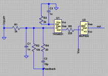
There is already an internal one.
Too small for such a high-GBW uncompensated beast like THS4021. Being realistically it could deliver without buffer, but namely this resistance disclose a whole page about stabilizing multistage followers.
Just look at simplified sch. Pairing them like a trick with stabilizing four stage emitter follower. Not so much could properly design even low-freq’ed EF3, so speaking about some dozens MHz EF4 are pure joke.
How you can live with drawing amplifiers as boxes in the schematic I'll never know 🙂. Makes me twitch.
What makes you use THS4021? Seems like there are other op-amps that are lower noise and distortion in the audio band that would be easier to use with the BUF634.
What makes you use THS4021? Seems like there are other op-amps that are lower noise and distortion in the audio band that would be easier to use with the BUF634.
Last edited:
- Home
- Vendor's Bazaar
- Updating a classic: BUF634A