How you can live with drawing amplifiers as boxes in the schematic I'll never know 🙂. Makes me twitch.
While we live drawing amplifiers as a Laplace functions then drawing them with a boxes are real enjoyment...
😉
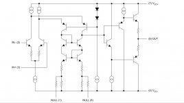
Draw a folded cascode loaded at a full-Wilson current mirror and followed by a parallel follower:

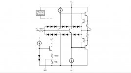
Bufferize it with additional parallel follower, say more powerful:

What makes you use THS4021?
Say your OPS (now - BUF634) provides -40 dB THD of 10 kHz tone. Wrapping a 80 dB depth feedback loop around that BUF634 provides you with something around -120 dB THD.
But at the same time that 80 dB loop wil demand some margins for stable operation. First of - really high bandpass of that BUF/OPS, so there are a classical tradeoff.
Seems like there are other op-amps that are lower noise and distortion in the audio band that would be easier to use with the BUF634.
AFAIK, no.
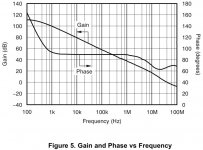
Typically 4021 provides you with at least 85 dB gain at 10 kHz. There are no comparative compensated opamp. You can swap it with only something like AD8067, LM7171, LT1222. Each of will be at least 20 dB better than common well-known “audio” opamps.
Last edited:
While we live drawing amplifiers as a Laplace functions then drawing them with a boxes are real enjoyment...
😉
Draw a folded cascode loaded at a full-Wilson current mirror and followed by a parallel follower:
View attachment 746707
Bufferize it with additional parallel follower, say more powerful:
View attachment 746708
Say your OPS (now - BUF634) provides -40 dB THD of 10 kHz tone. Wrapping a 80 dB depth feedback loop around that BUF634 provides you with something around -120 dB THD.
But at the same time that 80 dB loop wil demand some margins for stable operation. First of - really high bandpass of that BUF/OPS, so there are a classical tradeoff.
AFAIK, no.
Typically 4021 provides you with at least 85 dB gain at 10 kHz. There are no comparative compensated opamp. You can swap it with only something like AD8067, LM7171, LT1222.
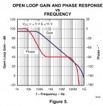
Yeah, it's decompensated. Is the standard result not good enough? I mean, you can get extremely good results with LME49xxx or OPA1611. I'd have to dig for some 10 kHz measurements with the BUF, but OPA1611 has almost 80 dB of gain at 10 kHz too, except it's unity gain stable without having to increase the noise gain.
Last edited:
Is the standard result not good enough?
Good, but boring...
Out of curiosity and greed...
I mean, you can get extremely good results with LME49xxx or OPA1611.
Yes, but what is extremely good? Compared with THD figures of the best of the best speakers each of our figures will be pretty good.
What about 130-140 dB depth around 100 mA biased OPS at 10 kHz? Bruno Putzeys wrote about and even shows pole-zero configuration. What if we could go further ahead?
OPA1611 has almost 80 dB of gain at 10 kHz too
Intrinsic gain - yes, but subtract external gain... Be sure, you’ll find that 15-20 dB handicap.
😉


Being in hostile EMI environment i’ll prefer to keep as much as possible feedback until “external antennas” could be effectively decoupled.
without having to increase the noise gain.
Yes, you are really understand.
Anyway we need some kind of common mode choke at the output, so most of noise could be effectively looped inside and it will be used for say dithering input stage.
Last edited:
Good, but boring...
Out of curiosity and greed...
Yes, but what is extremely good? Compared with THD figures of the best of the best speakers each of our figures will be pretty good.
What about 130-140 dB depth around 100 mA biased OPS at 10 kHz? Bruno Putzeys wrote about and even shows pole-zero configuration. What if we could go further ahead?
Intrinsic gain - yes, but subtract external gain... Be sure, you’ll find that 15-20 dB handicap.
😉
View attachment 746719
View attachment 746720
Being in hostile EMI environment i’ll prefer to keep as much as possible feedback until “external antennas” could be effectively decoupled.
Yes, you are really understand.
Anyway we need some kind of common mode choke at the output, so most of noise could be effectively looped inside and it will be used for say dithering input stage.
I see, it makes sense if you are aiming for the sky. 🙂
Do you happen to have a link to what Bruno wrote?
I see, it makes sense if you are aiming for the sky. 🙂
Well, you know, not everyone is playing in the sandbox with **** and sticks.
😀
Do you happen to have a link to what Bruno wrote?
You got PM.
I hope this thread hijacking didn't scare off Johnc124 ...
Maybe you guys should start a new thread on your projects?
Jan
Maybe you guys should start a new thread on your projects?
Jan
I hope this thread hijacking didn't scare off Johnc124 ...
Maybe you guys should start a new thread on your projects?
Jan
I'm still here!
I hope this thread hijacking didn't scare off Johnc124 ...
Maybe you guys should start a new thread on your projects?
Jan
Good call, maybe a mod can move those posts.
In the OPA1656 there are two applications: one for a RIAA preamp, using just the 1656, and a headphone preamp using the OPA1656 and a BUF634A combo.
Now that arrangement seems to be quite similar to what Gary Galo and Walt Jung used on their RIAA preamp.
On that case they also used a FET opamp for first stage, the AD745, an ultra low noise chip, and the LT1010 as buffer.
It looks as if this newer combo deserves a try as RIAA preamp too.
Now that arrangement seems to be quite similar to what Gary Galo and Walt Jung used on their RIAA preamp.
On that case they also used a FET opamp for first stage, the AD745, an ultra low noise chip, and the LT1010 as buffer.
It looks as if this newer combo deserves a try as RIAA preamp too.
I have 2 questions.
1.Some years ago I was seeking spice model for BUF634 in Low-Quiescent Current Mode. I failed. How about 634A?
2.Is there anywhere a more adequate schematic of 634(A) than in datasheet? Like, say, in http://images.100y.com.tw/pdf_file/33-ELANTEC-EL2009C.pdf
1.Some years ago I was seeking spice model for BUF634 in Low-Quiescent Current Mode. I failed. How about 634A?
2.Is there anywhere a more adequate schematic of 634(A) than in datasheet? Like, say, in http://images.100y.com.tw/pdf_file/33-ELANTEC-EL2009C.pdf
I have 2 questions.
1.Some years ago I was seeking spice model for BUF634 in Low-Quiescent Current Mode. I failed. How about 634A?
2.Is there anywhere a more adequate schematic of 634(A) than in datasheet? Like, say, in http://images.100y.com.tw/pdf_file/33-ELANTEC-EL2009C.pdf
We are working on spice models which show the full range of bias options, I'm hoping we'll have those online soon after the BUF634A RTMs (VERY soon).
Regarding the schematic, we got clever with the architecture of the BUF634A, and there is some IP that we would like to protect. The simplified schematic will have to do.
In other news, the full production datasheet is now available for download on the BUF634A product page.
John, any chip changes from the -X?
Jan
Nope! Only difference is that the production version won't have an "X" on the top of the package.
We are working on spice models which show the full range of bias options, I'm hoping we'll have those online soon after the BUF634A RTMs (VERY soon).
.
Apologies for the jargon: RTM = Release to Market. I'm on travel and have been in meetings all day so my brain is a little slow...
I have a question related to the datasheet.
Short-circuit current, is that peak current or RMS current and over which time span?
Short-circuit current, is that peak current or RMS current and over which time span?
I have a question related to the datasheet.
Short-circuit current, is that peak current or RMS current and over which time span?
Short circuit current is the amount of current that will flow out-of or into the device when the output is shorted to ground (forced to 0V). Generally we place a DC voltage on the input, short the output to ground, and measure the current flowing through the short. As you can see from the plots in the datasheet, as the die warms up in this condition the current flowing through the short will decrease, and the rate at which that occurs will really depend on the power supply voltage and thermals of the PCB. If the die gets too warm (about 175C) the thermal shutdown circuitry will kick-in and shut off the output transistors so the load current will drop to zero until the part cools off.
Gentlemen, I have a question about sample order. In "My TI" I receive error message
"Your company or university does not have access to order free samples from Texas
Instruments. If you have reached this page, you have been declined access to place
sample orders." The new buffer is not listed at the local shops. Thank you.
"Your company or university does not have access to order free samples from Texas
Instruments. If you have reached this page, you have been declined access to place
sample orders." The new buffer is not listed at the local shops. Thank you.
That tends to happen if you use a Yahoo, Gmail, Hotmail, etc. account. I haven't had any trouble with .edu addresses or email@mydomain.com type addresses.
Tom
Tom
Tried again with my email address from local technical university (but no .edu ending), still no success.
In the TI "support centre" there is a link "Request access to TI's sample program", waiting what happens.
In the TI "support centre" there is a link "Request access to TI's sample program", waiting what happens.
TI has meanwhile a very bad customer service. This has nothing to do with e-mail addresses. I also wanted to order some sample chips via my TI account. I said that they were for an evaluation and I would advertise on the net for them afterwards. The TI employee rejected everything completely. Yes, there are other chip manufacturers.
- Home
- Vendor's Bazaar
- Updating a classic: BUF634A