OPA1656 prelim datasheet is up on the web now
http://www.ti.com/product/OPA1656
I'll update this thread or make a new one when the sample button goes active (can take a couple of days)
http://www.ti.com/product/OPA1656
I'll update this thread or make a new one when the sample button goes active (can take a couple of days)
I have some applications that now use the 'old' BUF634 but need definitely the TO220-5pin or SMD equivalent, for thermal reasons
Same here. And dpak is easier to solder for an hobbyist than something with a thermal pad underneath. So my preference for that package.
But I'm a small fish so I understand that ti had to see what's making sense wrt the potential market.
Last edited:
No noise plot in DS ?
Patrick
Patrick there is one on the first page, is that useful?
Jan
Same here. And dpak is easier to solder for an hobbyist than something with a thermal pad underneath. So my preference for that package.
But I'm a small fish so I understand that ti had to see what's making sense wrt the potential market.
Yes. I use a combined footprint.
Jan
Attachments
OPA1656 prelim datasheet is up on the web now
http://www.ti.com/product/OPA1656
I'll update this thread or make a new one when the sample button goes active (can take a couple of days)
Hi John, how do the THD and IMD compare with the OPA2156 into a 600 Ω load?
Hi John, how do the THD and IMD compare with the OPA2156 into a 600 Ω load?
OPA1656 will perform slightly better than OPA2156 in those tests. The higher gain bandwidth product of the OPA1656 gives it about 6 dB more loop gain, resulting in lower distortion.
OPA1656 prelim datasheet is up on the web now
http://www.ti.com/product/OPA1656
I'll update this thread or make a new one when the sample button goes active (can take a couple of days)
That is a fantastic part, and only USD 1.05 for a dual. Thanks for making it happen....
That is a fantastic part, and only USD 1.05 for a dual. Thanks for making it happen....
Thanks for the encouraging words! Looking forward to seeing what people here build with the new parts.
John, I was wondering what influence the quiescent current setting on the BUF634 has on the distortion performance? Intuitively one could think that higher bias towards class A with respect to the load current would decrease THD, but is that always the case?
I have some indication that it's more subtle than that.
Jan
I have some indication that it's more subtle than that.
Jan
That's a great question Jan, I've actually been wondering the same thing. I have one of the new BUF634A EVMs in my office and can try to take some measurements at different bias settings this week. Or see if one of my applications engineers has some time to do it.
I could see the intrinsic distortion of the BUF634A not changing significantly with bias. But because its bandwidth does vary significantly with bias, the amount of loop gain that you're able to put around it in the system will be significantly less in low bias mode. Hence the distortion of the full composite circuit might be worse in low bias mode. Unless you started playing tricks with the compensation of the composite amplifier.
I could see the intrinsic distortion of the BUF634A not changing significantly with bias. But because its bandwidth does vary significantly with bias, the amount of loop gain that you're able to put around it in the system will be significantly less in low bias mode. Hence the distortion of the full composite circuit might be worse in low bias mode. Unless you started playing tricks with the compensation of the composite amplifier.
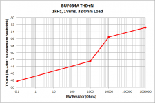
I was able to have an engineer measure the THD of a BUF634A at 4 different bias points today to see how THD changes with the bias current. He measured the THD at 1Vrms, into a 32 ohm load. The bandwidth pin was configured in 4 ways:
1. Open / floating
2. Shorted to V-
3. 1kOhm resistor to V-
4. 10kOhm resistor to V-
This THD measurement is done open loop, so the BUF634A is not inside the feedback loop of another amplifier. Results are attached, there is about a 15 dB difference in THD in the wide bandwidth mode (BW connected to V-) and THD in the low power mode (BW open / floating).
Edit to add: In the graph, the shorted case (wide bandwidth) is marked as 0.1 ohms, and the open case is 1MOhm. I just did this to all all the data points to be plotted vs resistance on a log x-axis
Attachments
Last edited:
John, thank you for that, very useful! I've done some tests also and what I thought was higher THD with higher bias appears to be the onset of low level oscillations due to the higher bandwidth and insufficient compensation.
Your graph makes a lot of sense, appreciated.
Edit: The embedded pic is unsharp when saved, is there a PDF you could attach to a post...?
Jan
Your graph makes a lot of sense, appreciated.
Edit: The embedded pic is unsharp when saved, is there a PDF you could attach to a post...?
Jan
Hi John,
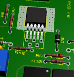
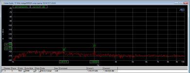
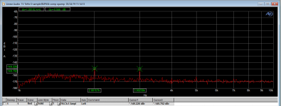
Did some more tests with a composite amp consisting of an AD797 and a BUF634. I now have two, one with a 'vintage' '634, one with one of the X-samples I got last week.
There's an interesting difference in harmonic structure. As mentioned, this is a sample size of one, but striking.
Comments?
Edit: Correction: I had the dBr sitting at 2.5V with 1V input, so the actuals are about 8dB worse than shown in the graph. Still respectable I think.
Jan
Attachments
Last edited:
I just ordered samples of the opa1656 and buf634a for building a headphone amp to compare to my favourit lm4562/lme49600 combi.
- Home
- Vendor's Bazaar
- Updating a classic: BUF634A