Thanks man. I'll try this first. 0.22ohm is critical? I thought I could also use Caddock's MP9100 (3.5W each air free) 2*0.1Ω=0.2 instead ... but very expensive 🙁
No, the 0.22 is not critical in this design.
I'm having 0.25Ohm there. I've chosen to go for 0.25 instead of 0.2 (4resistors in parallel instead of 5) because I haven't matched those otput devices.
I'm having 0.25Ohm there. I've chosen to go for 0.25 instead of 0.2 (4resistors in parallel instead of 5) because I haven't matched those otput devices.

Before I recap (I miss the 100µF/10V ones), I tested the 47nF (just some ceramic from the drawer) tip over the bias resistor: it did half the job  : no more oscillations neither when I plug the output power cables alone or with the fully loaded passive filter.
Although the oscillations remain when I load the amp only with the bass speaker (Z=8Ω, R=5.7Ω L=2.2mH), or with the passive filter when I remove the tweeter.
: no more oscillations neither when I plug the output power cables alone or with the fully loaded passive filter.Although the oscillations remain when I load the amp only with the bass speaker (Z=8Ω, R=5.7Ω L=2.2mH), or with the passive filter when I remove the tweeter.
Attachments
Not enough load at hf ? Increase the zobel cap value ?or with the passive filter when I remove the tweeter.
~ 68µF is ok? I found in wikipedia that zobel C is L/R², for me 0.0022/5.7² ? Thank you for been there for me man.
BTW, I found from here your fine protection circuit.Did you do one for mono block?
BTW, I found from here your fine protection circuit.Did you do one for mono block?
The Zobel: 0.022µ. You can try 0.033 or more.~ 68µF is ok? I found in wikipedia that zobel C is L/R², for me 0.0022/5.7² ? Thank you for been there for me man.
BTW, I found from here your fine protection circuit.Did you do one for mono block?
Did-you have 0.22Ohms non inductive resistances at sources of your power FETS ?
About my protection, just remove the non used parts form the schematic.
Hi 'Toph
Yes I had. But now they are 4*5 Vishay-Dralotic non inductive 1Ω metal film PR02.
I will try your tip to increase the zobel cap, con! 😉
The strange is that the amp ran in oscillation just when I plugged a simple-XLR-cable-without-no-load-at-all on the outputs (USE<HAR>H07RN-F 3*2.5mm², 5 meters long, 1 conductor between 2-2 and the two others between 1-1 to get some 2*3.75mm² equivalent)... maybe a strange load for the amp from a HF point of view?
Cool  Esperado, I added // a 15nF over the 22nF, no more 2MHz oscillation, even when I remove the 47nF from the bias P1. Although, not enough with bottom door shield mounted just close to the input. 47nF removed oscillation with the shield mounted, and 56nF removed all issues with shield and the passive filter and no tweeter or with just with the boomer or not load at all 🙂
Would you advise to increase the rated power for the 10Ω Zobel now the capa is more than twice the initial value? e.g. 3W PR03 (I don't know how to calculate this).
I shall now tweak the 2nd channel and check if hum is still here. Do you know a small audio frequencies generator for PC please?
Thanks again for your help man!
Esperado, I added // a 15nF over the 22nF, no more 2MHz oscillation, even when I remove the 47nF from the bias P1. Although, not enough with bottom door shield mounted just close to the input. 47nF removed oscillation with the shield mounted, and 56nF removed all issues with shield and the passive filter and no tweeter or with just with the boomer or not load at all 🙂Would you advise to increase the rated power for the 10Ω Zobel now the capa is more than twice the initial value? e.g. 3W PR03 (I don't know how to calculate this).
I shall now tweak the 2nd channel and check if hum is still here. Do you know a small audio frequencies generator for PC please?
Thanks again for your help man!
No need. if your amp is stable, there will be very little power in the resistance.Would you advise to increase the rated power for the 10Ω Zobe
Condenser in // with the zeners and bias potentiometer are just here to reduce zener and pot noise and impedance. You can // any value you want, but remember, as the 100µf is an electrolytic, it has an inductive impedance in it. Paralleling with film caps can high the result impedance at hf, this self // with your film cap is a resonating circuit. If your value makes your amp stable, everything OK.
Test your amp with 10Khz square waves to be sure no ringing on the front edges.
Google is your friend: By example NCH Tone generator...Do you know a small audio frequencies generator for PC please?
Thanks Esperado
In the time elapsed I also found this one LF-Generator free and stand-alone: Generator Quick Doc at VB-Audio software. I just saw the square waves are poor quality (maybe my sound card, and I'd rather not buy a licence before I'm sure it will work fine in my PC) but I didn't dig further because I focuse now (oscillations seem to be a bad memory) around the remaining hum issue, if you remember my first post.
As I said, I suspected a ground loop, and I found yesterday something very strange for me: it seems to be a ground loop.
First I must say the amp "shows" the same hum with another stereo preamp (also un-earthed too) and other cables (shorter).
The strange is that hum is here only when the 2 input cables are plugged, even when I break the ground in one cable, whatever side amp or preamp, just the same, right and left. When I unplug one cable, just keeping one grounded on both sides, the hum disappears fully even with the long 8m cables. It seems the "ground" loop runs through the hot input contact(s)
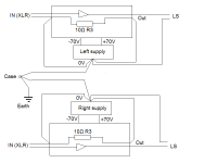
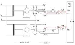
I attach here a schema of the ground in my cabling, showing the 10Ω R3 (not the Zobel one). Maybe you could point me an error I made. I checked again Elektor's schematic, I can't see any difference but I have 2 independant supplies, only linked through case/earth.
So I checked the phase on the 2 rectifier bridges in the supplies and I found they were inverted according to the colors of the transformers output wires, which wouldn't seem critical to me, but I wired them the very same way and I also checked the primary coils of the transformers are in same phase...by chance they were... but still the same hum.
Then I tried to un-earth one side or the other of the amp .... -> huge silence 🙂 but 😕
When I was running these tests, manually earthing/unearthing (I mean without the help of screw/nut) I saw little sparks, so I suspected isolation issue. I measured >200MΩ between case and both grounds when I un-earth both sides, and strange 40/80 (and even 160 200 VAC with the preamp plugged).
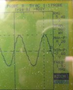
Ho, surely important, I also attach a picture of the hum on both sides I caught before I change the bridges wiring: 100Hz, but not at all a rectified sine wave, and neither not at all the aspect of a bi-alt filtered supply. On the other channel, the mountains were negative at same phase... as long as I can use a scope 😱
Any idea please?
In the time elapsed I also found this one LF-Generator free and stand-alone: Generator Quick Doc at VB-Audio software. I just saw the square waves are poor quality (maybe my sound card, and I'd rather not buy a licence before I'm sure it will work fine in my PC) but I didn't dig further because I focuse now (oscillations seem to be a bad memory) around the remaining hum issue, if you remember my first post.
As I said, I suspected a ground loop, and I found yesterday something very strange for me: it seems to be a ground loop.
First I must say the amp "shows" the same hum with another stereo preamp (also un-earthed too) and other cables (shorter).
The strange is that hum is here only when the 2 input cables are plugged, even when I break the ground in one cable, whatever side amp or preamp, just the same, right and left. When I unplug one cable, just keeping one grounded on both sides, the hum disappears fully even with the long 8m cables. It seems the "ground" loop runs through the hot input contact(s)
I attach here a schema of the ground in my cabling, showing the 10Ω R3 (not the Zobel one). Maybe you could point me an error I made. I checked again Elektor's schematic, I can't see any difference but I have 2 independant supplies, only linked through case/earth.
So I checked the phase on the 2 rectifier bridges in the supplies and I found they were inverted according to the colors of the transformers output wires, which wouldn't seem critical to me, but I wired them the very same way and I also checked the primary coils of the transformers are in same phase...by chance they were... but still the same hum.
Then I tried to un-earth one side or the other of the amp .... -> huge silence 🙂 but 😕
When I was running these tests, manually earthing/unearthing (I mean without the help of screw/nut) I saw little sparks, so I suspected isolation issue. I measured >200MΩ between case and both grounds when I un-earth both sides, and strange 40/80 (and even 160 200 VAC with the preamp plugged).
Ho, surely important, I also attach a picture of the hum on both sides I caught before I change the bridges wiring: 100Hz, but not at all a rectified sine wave, and neither not at all the aspect of a bi-alt filtered supply. On the other channel, the mountains were negative at same phase... as long as I can use a scope 😱
Any idea please?
Attachments

First, the grounds of supplies capacitances have to be connected together in the same point, or with a Coper plate, or with big diameter wire as short as possible. From this point are kept all the grounds of the amps, the earth of the chassis, the ground from The input RCAs.
Of course, RCA's ground need to be isolated from the chassis.
Too, verify the good health of your main diodes.
Of course, RCA's ground need to be isolated from the chassis.
Too, verify the good health of your main diodes.
Last edited:
Some news
I think I will rewire my supplies, now I fully recaped the amps.
I discovered I reached to dramatically reduce the hum (noise in LS lower than the transformers mechanical one) this way:
1) leave the metal chassis earthed for security purpose.
2) insert a small value resistor in the connection between each ground to the chassis.
Best result being around ~100~200Ω, I can measure low AC voltage between chassis and both ground:
33Ω -> 7mV
68Ω -> 11mV
100Ω -> 15mV
150Ω -> 22mV
200Ω -> 29mV
keep in mind I have 2 separated supplies, one for each amp and input jacks are XLR, meaning input grounds signal (pins1+3) are NOT linked to the chassis.
Before I work on rewiring, I'd like to know the best way. I draw 3 ways below, please could you advise?
The first (upper one) may appear as a RCRCR filter, considering the wire resistance, but is not a star 🙁
Thanks
Attachments

Hi, HumNSmoke.
Take the following precautions: Use a filtering AC plug against RFI/EMI.
Work around your diode bridge to remove oscillation and spikes generated by their switching.
Insert a cardboard of some thickness between trasfo and chassis to reduce capacitance to the chassis.
Try to invert the AC wires and chose the arrangement with less V on your ground resistance. Remove the ground resistance.
Use your n° 3 design for a star common point. It has to be the same for the both amps and power supplies. Use BIG wires if you cannot use a coper plate to wore the big caps..
Isolate your RCA ground from the chassis. Use a shielded cable between the rca and amp board. Don't connect the shied amp side. Connect a wire between ground of the RCA and star ground. etc...
Everything has to be referenced to the star point.
Hi, HumNSmoke.
1) Take the following precautions: Use a filtering AC plug against RFI/EMI.
2) Work around your diode bridge to remove oscillation and spikes generated by their switching.
3) Insert a cardboard of some thickness between transfo and chassis to reduce capacitance to the chassis.
4) Try to invert the AC wires and chose the arrangement with less V on your ground resistance. Remove the ground resistance.
Use your n° 3 design for a star common point. It has to be the same for the both amps and power supplies. Use BIG wires if you cannot use a coper plate to wore the big caps..
5) Isolate your RCA ground from the chassis. Use a shielded cable between the rca and amp board. Don't connect the shied amp side. Connect a wire between ground of the RCA and star ground. etc...
Everything has to be referenced to the star point.
Hi Christophe
1) I just had a look at radiospare's EMI filters. I really don't know what to choose. Looking at characteristics, I see that using a filter may be "worse than better" as they often show negative attenuation !!! between 10 and 100kHz for some crytpic conditions to me, and 0dB below 😕 ... and I'd rather not not use a mains symetriser, because I will have later a earthed computer and related stuff and UPS linked to the audio system, and no optical isolation capabilities in the preamp
2) I'll will look at this when I get the scope back. In fact, as I use one 4 diodes bridge for each amp, this may be different from the Elektor genuine design, I'm not sure.
3) Already done: my "huge-bigMAC" recipe: Screw M8*150mm - M8 washer - Alu 145*145*3mm square washer - Iron case - Wood 140*140*5mm square washer - Rubber washer - transfo left - Rubber washer - Wood 140*140*5mm square washer - Rubber washer - transfo right - Rubber washer - Wood 140*5mm washer with a big ~50mm hole - Iron 110mm transfo washer - M8 washer - M8 nut ... with NO loop back to the case : bon appétit 😉
4) Already tried this: now with ground-earth resistances removed (=multimeter 10MΩ), I get 40/80Vac depending on the way I plug the preamp mains cable, when before I got 80/200Vac. But still big hum only when R=0Ω from star to case and both preamp cables plugged.
5) "Isolate your RCA..." no need : XLR, so ok here
"Use a shielded cable..." like in genuine design: I use ~20/30cm
"Don't connect the shied amp side. Connect a wire between ground of the <s>RCA</s>XLR and star ground." OK, this makes sense to me : return signal ground to source preamp won't run anymore along the 20*30cm shield (at least inside the amp, but what about the 1 to 8m outside? Should I consider switching to symetrical links). BTW, please just confirm: this new wire is really an additional one from the star to the XLR, not a replacement of the one that goes from the star to the board ground "In", isn't it?
Thanks for tips man
Attachments
Last edited:
Hi, HumNSmoke.
You are on the right track.
First of all, you have to be sure that your amps do not oscillate, event at very high frequencies, under your normal loudspeaker loads. Hearing a "crrr" little noise can be an indication of it.
About input cables, my tips implies a symmetrical cable. (two wires under the shield). Chose cables with enough coper inside.
You can try, as an alternative, to use normal rca cables, don't connect the shield amp side, and provide a separate big diameter cable betwwen the two chassis.
Too try to add a ground connection from your preamp to AC outlet and play with the relative sens of your ac plugs: Once you have chosen the sens in your amp that produce the less current across the ground ac wire, dont connect the preamp to amp, try to invert the preamp AC wires while measuring voltages between the two chassis. Chose the position with the less leakage.
Last edited:
As explained on the original article the amp compensation rely
on the fets input capacitances to providing a shunt compensation ,
an hazardous "solution" that will leave some builders chasing ghosts...
To be stable enough without relying on the said random parameters
two compensation caps , about 22pF each , should be implemented
from inputs to outputs of the cascodes.
Reducing the slew rate and closed loop bandwidth of the amp to 400khz at -3db !!!To be stable enough without relying on the said random parameters two compensation caps , about 22pF each , should be implemented from inputs to outputs of the cascodes.
Last edited:
No , the -3db point would still be in the Mhz range but it would suppress
an exagerated gain overshoot wich was adressed in later Elektor designs
by implementing a pole canceling network between collectors of the
respective differentials.
Below is the CLG without and with the said caps.
an exagerated gain overshoot wich was adressed in later Elektor designs
by implementing a pole canceling network between collectors of the
respective differentials.
Below is the CLG without and with the said caps.
Attachments
Last edited:
- Home
- More Vendors...
- Elektor
- Update for Elektor Crescendo Power Amplifier 1982