bjornogain 180w amplifier
dear sir,
can some one send me 180 w amplifier pcb as above mentioned.at
khan.shahid251@gmail.com
thanking you
dear sir,
can some one send me 180 w amplifier pcb as above mentioned.at
khan.shahid251@gmail.com
thanking you
I sent a copy of the pcb layout to your personal email address. Please note, that the MOSFETs in the output stage must be mounted directly on the pcb, with an L profile of aluminium between the MOSFETs and a decent heatsink. The schematic has been already published in this thread. Good luck!
dear oodi sir i saw your mini crescendo attached thumbnail.for seing this i compare my kit .so plz.show your complete diagram such as protector circuit as it peep in in yor thubnail. my e mail khan.shahid251@gmail.com
Hello,
I don't have a schematic for this protection circuit. But it is simple to develop one. You need a power on reset, which can be done with an NE555 timer. Secondly, you need to rectify the output from the power stage, low pass filtered to remove any audio frequency. Take a DC transistor amp, connect it to a relay which switches the connection between your speakers and your power amp. This can be soldered on a breadboard. And forget the DC protection from Elektor. This circuit does not work properly. You can also take a HA12002. The datasheet is available on the internet.
HA12002 pdf, HA12002 description, HA12002 datasheets, HA12002 view ::: ALLDATASHEET :::
Holger
Ultimate modification of Crescendo
Or how to get 1500V/µs and 10Mhz of bandwidth, with increased stability, simply in changing some resistances values and... Removing two transistors.
A way to demonstrate the advantages of the Current Feedback topology against Voltage controlled feedback.
Thanks for the fantastic Lazy Cat for his help .
http://www.diyaudio.com/forums/elek...ack-mod-electktors-crescendo.html#post2734172
Moved here:Or how to get 1500V/µs and 10Mhz of bandwidth, with increased stability, simply in changing some resistances values and... Removing two transistors.
www.esperado.fr - Le crescendo revisité
Hi,
I also built these beasts about 25 years ago. I modfied them, according to the supplements by ELEKTOR, and I added 7 volts on both supply rails for the driver section, as given by the GIGANT amp. The only problem I encountered with is hum, as already mentioned above. Fortunately I have no problems at all with oscillations. The amps (I built a stereo version with separate power supplies for each channel) simply work as it should. Total output power just before clipping ist well over 300 watts @ 4 Ω per channel, due to the increased driver supply voltages.
And yes, the CRESCENDO is not undestructible: As my elder son connected a bunch of speakers to it, with no respects on the total impedance, he blew both power MOSFETs of one side of one channel. This fortunately was the only thing I had to fix until now.
Interested in pics of my amp?
Best regards
Hi,
I also built these beasts about 25 years ago. I modfied them, according to the supplements by ELEKTOR, and I added 7 volts on both supply rails for the driver section, as given by the GIGANT amp. The only problem I encountered with is hum, as already mentioned above. Fortunately I have no problems at all with oscillations. The amps (I built a stereo version with separate power supplies for each channel) simply work as it should. Total output power just before clipping ist well over 300 watts @ 4 Ω per channel, due to the increased driver supply voltages.
And yes, the CRESCENDO is not undestructible: As my elder son connected a bunch of speakers to it, with no respects on the total impedance, he blew both power MOSFETs of one side of one channel. This fortunately was the only thing I had to fix until now.
Interested in pics of my amp?
Best regards
can you upload schematics,pictures of it ?
thank
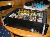
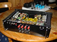
Hi dungdochi,
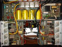
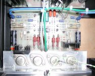
finally here are some pics of my CRESCENDO stereo power amp. Have fun and thanks for waiting!
Best regards
finally here are some pics of my CRESCENDO stereo power amp. Have fun and thanks for waiting!
Best regards
Attachments
I sent a copy of the pcb layout to your personal email address. Please note, that the MOSFETs in the output stage must be mounted directly on the pcb, with an L profile of aluminium between the MOSFETs and a decent heatsink. The schematic has been already published in this thread. Good luck!
dear holger,
happy new year.as u mentioned that u have sent a copy on my personnel e mail i have not received such type of pcb.sorry for bother you.thanking u.
your ever masood
happy new year.as u mentioned that u have sent a copy on my personnel e mail i have not received such type of pcb.sorry for bother you.thanking u.
your ever masood
thank
So look not nice, seem almost need maintance. but i dont want it more ,now i want build up A1000 amp & F5 of nelson pass. Because it is fully class A. QUALITY. if you have more expeirient do it can send it to me.
Thank you
Hi dungdochi,
finally here are some pics of my CRESCENDO stereo power amp. Have fun and thanks for waiting!
Best regards
Very well build, looks good. Must be 20 years old or so?
jan didden
Hello Jan,
I've built it in 1985 or so, using lots of components out of my scrapboxes.
Best regards!
I've built it in 1985 or so, using lots of components out of my scrapboxes.
Best regards!
Hi hot tip guys
I did it in 83/84 and used it for 10 years, then I moved in a little house where I didn't have room enough to host it... the beast is huge and heavy 30kg...
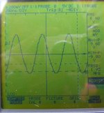
Some days ago I decided to bring it back to life after a 15 years sleep in the idea to use it as the bass amp for an active 3 ways system around a DCX2496, but I noticed after removing the dust that there was hum in the speakers as soon as I plugged in the second input, left or right. I broke the ground in one cable and also isolated the earth.... still same behaviour... the I saw R32 comes very hot when I plug the output wires (checked for short-cuts)... although, the amp works on both channel even together, and DC out seems OK on one (20mV) and the other seems to near to zero to be honest
I never watched the outputs with a scope so I asked a friend to lend me one and I saw a "nice" 2MHz sinus as soon as I plug a wire on the outputs, even with-w/o the speakers... and even with the passive filters .
My amp is a bit tweaked: I didn't wired the 470VA transfos like in Elektor. Instead I used one for each channel with the idea to be able later to have the two channels completely independent from each other.
Any advise please?
Thank you in advance.
I did it in 83/84 and used it for 10 years, then I moved in a little house where I didn't have room enough to host it... the beast is huge and heavy 30kg...
Some days ago I decided to bring it back to life after a 15 years sleep in the idea to use it as the bass amp for an active 3 ways system around a DCX2496, but I noticed after removing the dust that there was hum in the speakers as soon as I plugged in the second input, left or right. I broke the ground in one cable and also isolated the earth.... still same behaviour... the I saw R32 comes very hot when I plug the output wires (checked for short-cuts)... although, the amp works on both channel even together, and DC out seems OK on one (20mV) and the other seems to near to zero to be honest
I never watched the outputs with a scope so I asked a friend to lend me one and I saw a "nice" 2MHz sinus as soon as I plug a wire on the outputs, even with-w/o the speakers... and even with the passive filters .
My amp is a bit tweaked: I didn't wired the 470VA transfos like in Elektor. Instead I used one for each channel with the idea to be able later to have the two channels completely independent from each other.
Any advise please?
Thank you in advance.
Attachments
[Edit]
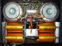
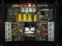
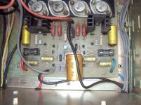
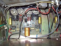
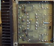
R32 on left channel rosted (one whole night under oscillation condition) the CF4 24/10mm stained 70µm copper.
Added pictures of :
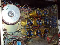
The supply: 4 rails 20mF/100V each (on the right bottom corner, the central and single link between left/right ground, case and earth
The CF4 side
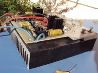
A different build with the same heatsink (parallel instead of right angle) I never tried, more compact but harder to maintain (heat tranfert aluminium piece 4mm under mosfets and 12mm over the heatsink)
R32 on left channel rosted (one whole night under oscillation condition) the CF4 24/10mm stained 70µm copper.
Added pictures of :
The supply: 4 rails 20mF/100V each (on the right bottom corner, the central and single link between left/right ground, case and earth
The CF4 side
A different build with the same heatsink (parallel instead of right angle) I never tried, more compact but harder to maintain (heat tranfert aluminium piece 4mm under mosfets and 12mm over the heatsink)
Attachments
Hi,
Welcome to DiyAudio!
If I see it correct, you are definitely using wirewound source resistors (0R22).
These are causing on all Crescendo's oscilation.
You should swap them to inductive free resistors (e.g. MPC71), or use 4 carbon resistors (also inductive free) as I did.
Greetz
Welcome to DiyAudio!
If I see it correct, you are definitely using wirewound source resistors (0R22).
These are causing on all Crescendo's oscilation.
You should swap them to inductive free resistors (e.g. MPC71), or use 4 carbon resistors (also inductive free) as I did.
Greetz
Attachments
- Home
- More Vendors...
- Elektor
- Update for Elektor Crescendo Power Amplifier 1982