
Minek,
I had not seen post #1594 - very good writing and more objective than subjective, as both of us prefer!
I think 'air' in a good recording comes back to resolution, and that is caused by strong, accurate gate drive on the outputs.
I think you are right about temperatures. Most amps with ambient temperatures rises around 20C mean heatsinks and since the thermal impedance from die to case and case to heatsink are quite large you'd expect case temps around 70C and in truth die temperatures over 100C. Since you can't see these temperatures they pass unnoticed, but they are the monsters which kill output devices. I like mosfets for Class A because they are thermally tougher than bipolars, although I have a notion that bipolars on Class A give more resolution.
This caught my eye, what are 'error vectors'?
HD
This caught my eye, what are 'error vectors'?
Check out this thread - very funny discussion between Alexander Petrov and the rest of the world.
https://www.diyaudio.com/community/threads/musings-on-amp-design-a-thread-split.366099/post-6763661
"Error vectors" came up several times, and no one had any idea what do they really mean 🙂
Check out this thread - very funny discussion between Alexander Petrov and the rest of the world.
https://www.diyaudio.com/community/threads/musings-on-amp-design-a-thread-split.366099/post-6763661
"Error vectors" came up several times, and no one had any idea what do they really mean 🙂
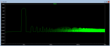
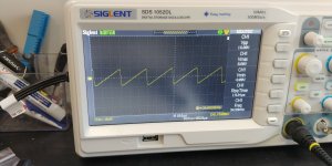
What is the purpose of the Hafler SWDT test? The meaning of the test is to subtract the input signal from the output signal attenuated by the divider to the input level, i.e. reduced in level to the input. It is also possible vice versa - to subtract from the output signal the input multiplied by Ku, i.e., the normalized signal. In both cases, we will get not real distortions, but only the so-called vector errors. To measure the actual introduced distortions, it is necessary to use a compensation testing method, which consists in subtracting from the output signal the normalized input signal, but delayed by the signal propagation delay time. In this case, the best test signal is triangular with a frequency of 10 kHz, processed by a low-pass filter with a frequency of 100 kHz. In this case, we will get all kinds of distortions, including high-speed distortions opposite the tops of the triangular signal.
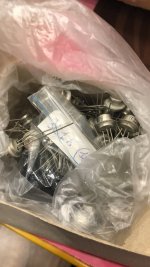
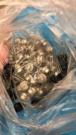
Good dayKT, 2T - Si
П, ГT, 1T - Ge
Soviet Union germanium transistors 🙂)(
Attachments
This schematic is little same with Xindak XA6800RThe crazy amp is supposed to be based on this circuit
Jfet input and Holton schematic plus output stage with common collector connection
What is the purpose of the Hafler SWDT test? The meaning of the test is to subtract the input signal from the output signal attenuated by the divider to the input level, i.e. reduced in level to the input. It is also possible vice versa - to subtract from the output signal the input multiplied by Ku, i.e., the normalized signal. In both cases, we will get not real distortions, but only the so-called vector errors. To measure the actual introduced distortions, it is necessary to use a compensation testing method, which consists in subtracting from the output signal the normalized input signal, but delayed by the signal propagation delay time. In this case, the best test signal is triangular with a frequency of 10 kHz, processed by a low-pass filter with a frequency of 100 kHz. In this case, we will get all kinds of distortions, including high-speed distortions opposite the tops of the triangular signal.
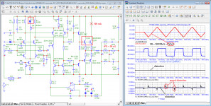
For greater clarity of speed distortions, I will give two examples of testing models that differ in Group Delay by 4 times
Attachments
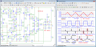
Here is a new amp with op-amp at the input, but this time with relatively normal, buffered VAS, and 2-pole compensation.
Looks promising - low distortions and stable (PM: 45, GM: 17). Slew rate 84 V/us.
I guess will be building it this summer..
Comments? Opinions? Improvements?

Looks promising - low distortions and stable (PM: 45, GM: 17). Slew rate 84 V/us.
I guess will be building it this summer..
Comments? Opinions? Improvements?
Attachments

Nice circuit, Minek!
Can you explain why you have taken the left side of C16 to emitter of Q1 and not to collector, and D3, which is clearly a protective diode but to me is probably redundant.
But it's a very good circuit and should be very good with very low THD and good offset.
Thanks for sharing it with us.
HD
Can you explain why you have taken the left side of C16 to emitter of Q1 and not to collector, and D3, which is clearly a protective diode but to me is probably redundant.
But it's a very good circuit and should be very good with very low THD and good offset.
Thanks for sharing it with us.
HD
It would also worked when connected to the collector - that's more 'normal' thing to do;
however when C16 is connected to the emitter of Q1, amps shows wider margin of being stable - better phase and gain margin. Also, the capacitance of C16 (and C17) can be lower in this case. I started with standard single pole compensation, but amp shows better characteristics with 2-pole.
I've seen this way of connecting compensation caps in couple of Russian amps, and it seems to work OK in this case, at least in the sim.
You think this protective diode is not needed?
Last edited:
I will attempt to answer...in most cases it should prevent rail sticking and or improve recovery time when the amp clips. You can verify by running a transient analysis at clipping level and see how it reacts. With diode vs without the diode.You think this protective diode is not needed?
Last edited:
Thank you Minek! Anything improving GM and PM are better; but from experience recently compensating a similar amp small such variations hugely change the sound presentation whilst at the same point making very little difference to bandwidth or ULGF, so it's a great opportunity to test it both ways.
Thanks de O, I think you are right. Perhaps it is a Bakers Clamp?
HD
Thanks de O, I think you are right. Perhaps it is a Bakers Clamp?
HD
It looks like it Sir Hugh, with simulation bav21 displays lower thd than any other diode when implemented as Bakers clamp.Thanks de O, I think you are right. Perhaps it is a Bakers Clamp?
HD
I like it, but here is my $0.02:
1. As you know me, I don't like the loss of supply swing to the FET vto voltages (etc). In this case you are losing 100-87= 13 VPP. The solutions I have posted before.
2. The main source of rail sticking is the op-amp over drive. I tried to clamp it, but it always resulted in distortion. What does work is reducing the op-amp voltages to 6.8V each. You could reduce the Positive supply to less except you need voltage for the input CMRR.
3. The baker clamp on a Darlington can be a normal silicon diode because the first base is two VBE from the emitter. This can be important when the supply voltages add up to more than the Schottky breakdown voltage, and it clips a tiny bit closer to the rail. Another important reason for a Baker clamp is to limit the VAS current that otherwise can cause phase inversion.
Thanx for posting something interesting. DIYA has been a bit boring lately, and sometimes temps me to post rude remarks. 😒
Steve, yeah, you are right that there is a loss of 13Vpp, but the thing is that:I like it, but here is my $0.02:
1. As you know me, I don't like the loss of supply swing to the FET vto voltages (etc). In this case you are losing 100-87= 13 VPP. The solutions I have posted before.
2. The main source of rail sticking is the op-amp over drive. I tried to clamp it, but it always resulted in distortion. What does work is reducing the op-amp voltages to 6.8V each. You could reduce the Positive supply to less except you need voltage for the input CMRR.
3. The baker clamp on a Darlington can be a normal silicon diode because the first base is two VBE from the emitter. This can be important when the supply voltages add up to more than the Schottky breakdown voltage, and it clips a tiny bit closer to the rail. Another important reason for a Baker clamp is to limit the VAS current that otherwise can cause phase inversion.
Thanx for posting something interesting. DIYA has been a bit boring lately, and sometimes temps me to post rude remarks. 😒
a) I'm designing 100W amp - I don't really need more power (bigger heatsink, psu, etc..)
b) I have a PSU already (I'm using the same PSU for all my amps), and it's +/- 50V - so all in all I'm getting my 100W
c) bootstrap capacitors will slightly increase distortion (as far as I can tell from sims..)
I guess better (?) solution would be to use +/- 42V rails for OS, and boosted rails +/-50V for input/VAS ?
Have to look up your proposed solution, I remember trying/simulating it several months ago...
I need to try your suggestion with lower supplies for the op-amp, this might be good idea..
BAV21 is not a Schottky, it's a regular small signal switching diode; as far I remember it has higher voltage (250V) and lower capacitance than 1N4148, and it's more commonly used for baker clamps.
I thought it was one of the Brig amps, but now I checked, and I guess it was not Brig.
Must have been something else..
Amp from the post https://www.diyaudio.com/community/threads/unusual-amp-from-1987.357369/post-7068145
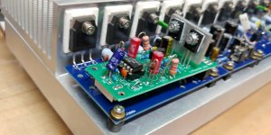
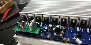
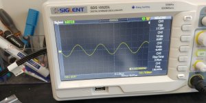
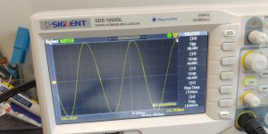
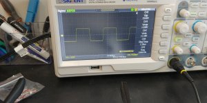
has been built (1 channel so far). Works like a champ. the only correction was to change C19 from 5pF to 9pF.
One channel built and tested so far. Will build 2nd channel, and then test with real music.
Idle current 40-50mA per output fet, output DC voltage (with C20 installed): 0.4 mV. Without out - 160mV.
Attachments
-
 20220811_205302.jpg248.2 KB · Views: 284
 -
 20220812_150847_HDR.jpg339.9 KB · Views: 204
 -
 20220813_104310.jpg319 KB · Views: 201
 -
 20220813_104338.jpg296.4 KB · Views: 186
 -
 20220813_104400.jpg286.1 KB · Views: 174
 -
 20220813_105828.jpg277.2 KB · Views: 183
 -
b44.ok.asc14.3 KB · Views: 128
-
 20220813_104549.jpg291.5 KB · Views: 254
Last edited:
Here are both channels completed, and playing music right now. All good.
Sounds great. Difficult to distinguish from any other amp built in the thread, but I would say it has more bass.


Sounds great. Difficult to distinguish from any other amp built in the thread, but I would say it has more bass.
Last edited:
- Home
- Amplifiers
- Solid State
- Unusual amp from 1987