H
HAYK
Your method of measuring the loop gain is wrong. The compensations must be included in the transfer function and not in the loop. The generator should be before R12 not R22.They sim very well, but I was unable to make them stable in real world.
Another error is when you use 2pole CRC.
Post in thread 'Linearizing the CFP crossover - P3a of Rod Elliot as example' https://www.diyaudio.com/community/...-of-rod-elliot-as-example.402148/post-7431662
The resistor must be either ground or rail but not from output. With inserted generator you do see a high pass function, but without, it becomes 1pole with a paralleled RC. Here again the compensation capacitor ,if from the output, should make part of the transfer function not the loop.
Last edited by a moderator:
Your method of measuring the loop gain is wrong. The compensations must be included in the transfer function and not in the loop.
The generator should be before R12 not R22.
You might be right here, Steve pointed this before if I remember correctly, when looking at some other of my amps.
Will retry sims. This amp is stable in real life, but perhaps can be stabler 🙂
There was some discussion about it, but kind of inconclusive... I was assuming that since this is global feedback (not local anymore, as compared to typical Miller cap), it should be included in the total feedback....
Another error is when you use 2pole CRC.
I don't think so.
There is many examples of this kind 2 pole CRC compensation.
Resistor definitely can go to the output (vs. going to the ground).
Example: Douglas Self's book, page 339 (6th edition) discusses such compensation in detail.
I've never seen this resistor to go the rail, but it's not impossible I guess.
Last edited:
Is that how you are proposing to locate the probe ?

This is how new OLG (without any other changes looks like):
PM: 27, GM: 14
Will experiment and try to improve it, and than validate in the real world.

Edit 1: Quick change of C6 value to 7pF, makes PM: 45.5 and GM: 9.7, so it's 'officially' stable..
Perhaps even better results are possible, will keep testing it.
New sim attached.
Edit 2: C6 = 8pF or 9pF seems even better. GM: over 50.
Thd and square waves still look great (same as before).
Noise floor in FFT plot went little bit up, if I can trust my eyes....
This is how new OLG (without any other changes looks like):
PM: 27, GM: 14
Will experiment and try to improve it, and than validate in the real world.
Edit 1: Quick change of C6 value to 7pF, makes PM: 45.5 and GM: 9.7, so it's 'officially' stable..
Perhaps even better results are possible, will keep testing it.
New sim attached.
Edit 2: C6 = 8pF or 9pF seems even better. GM: over 50.
Thd and square waves still look great (same as before).
Noise floor in FFT plot went little bit up, if I can trust my eyes....
Attachments
Last edited:
Added 4pF caps to C6 on both input boards (so C6 in total is 8pF) , and amp still works like a charm.
No difference observed so far, but if this method of placing the probe is more correct, so be it.
Will listen to more music tomorrow
May want to retry siming and then testing of some previously unstable amps, perhaps it will help them.
No difference observed so far, but if this method of placing the probe is more correct, so be it.
Will listen to more music tomorrow
May want to retry siming and then testing of some previously unstable amps, perhaps it will help them.
H
HAYK
Looking on the self book, the ac input signal of RI is the same as that of C13. By this the RiC13 is not a high-pass function, just parallel in series with the C3. Hence C3 alone is active as Cherry's compensation. If you replace the C13 with RI and get the Ri to ground or -V, then you get 2pole.
LKA has an exemplary of 3pole compensation, you can see two grounding resistors.
Thread 'Single supply, three-pole compensated class-B retro amp' https://www.diyaudio.com/community/...ee-pole-compensated-class-b-retro-amp.385080/
LKA has an exemplary of 3pole compensation, you can see two grounding resistors.
Thread 'Single supply, three-pole compensated class-B retro amp' https://www.diyaudio.com/community/...ee-pole-compensated-class-b-retro-amp.385080/
H
HAYK

The ac input signal of RI is NOT the same as that of C13. The signal from RI is delayed/filtered by the pole(s) of the EF stages. The second pole depends on the EF response and C13, RI need to be chosen to cancel the EF pole.
H
HAYK
As yourself remark, it doesn't generate a pole but some remedies for the EF pole in general about 20Mhz.
In the range of the loop gain pass band, bellow 20khz the Ri and C13 have very small difference not enough to provoke high pass function of the output signal.
In the range of the loop gain pass band, bellow 20khz the Ri and C13 have very small difference not enough to provoke high pass function of the output signal.
I have QA401 analyzer, but it seems it has 130dB noise floor, so I can't see the real noise floor.I would be very interested to know what you measure as signal noise distance.
All me amps I built within last few years, usually show the same numbers....

The output bias is sensitive to VAS current which is sensitive to the stage before... Maybe a tweak to the VBE multiplier could improve that?
I thought that all typical Vbe multipliers are sensitive to the current of previous stage.
That would be nice if we have improved multiplier, any suggestions here?
My best idea is a two-stage (~CFP) VBE multiplier that has a flatter V/I curve. There is also the small resistor in the collector idea, but I think it has a limited current range. There are push-pull VAS topologies that are relative insensitive to IPS current, but then you have a different circuit.
I was revisiting some of 'failed' amps from my junk box, and this amp came up - apparently I soldered BC transistors with C/E swapped
(so they were positioned like 2N transistors, which have different pinout). At the time (1 year ago), I didn't discover this fact.
Now I did; re-soldered 2 little BC transistor rotating them by 180 degrees, and voilà - the amp works like a champ.
Had to increase value of the feedback cap (squares were not perfect), and everything seems OK.
Idle current 45mA per fet, op-amp: TL071, Phase Margin: 52 degrees, Gain margin: 9.
Simulated slew rate: 150 V/us.
As for topology - it's a cross of Philips 22ah578 input (op-amp + Q1/2) , plus Hawksford cascoded VAS (Q3/4/8/9).

Now it's time to assembly 2 channel, and do music tests.
(so they were positioned like 2N transistors, which have different pinout). At the time (1 year ago), I didn't discover this fact.
Now I did; re-soldered 2 little BC transistor rotating them by 180 degrees, and voilà - the amp works like a champ.
Had to increase value of the feedback cap (squares were not perfect), and everything seems OK.
Idle current 45mA per fet, op-amp: TL071, Phase Margin: 52 degrees, Gain margin: 9.
Simulated slew rate: 150 V/us.
As for topology - it's a cross of Philips 22ah578 input (op-amp + Q1/2) , plus Hawksford cascoded VAS (Q3/4/8/9).
Now it's time to assembly 2 channel, and do music tests.
Attachments


Last edited:
Both channels finished, and enthusiastically playing music.
When building 2nd channel I had to make small change: green LED D3 that was biasing Q1/Q2 was replaced by small Zener 2V2.
It turned out that I don't have the same green LEDs anymore, and the new ones I have, have slightly different Vf, so 2nd channel
would not match the 1st one as far as VAS current goes. The current would be too high..
Another solution would be to use red LED + resistor with a value, so voltage between bases of Q1/Q2 is 2.2V.
Or adjust R15/R16.
Since this amp reminds me strongly that Christmas is coming, I thought there is enough illumination already,
and went for a Zener instead...
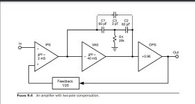
Regarding amp from post #1709 (Hafler P7000), here is better explanation how it works, from
Arto Kolinummi execllent book "Audio Power Amplifiers".
I'm listening to this amp, and I like it more and more.
When measuring square waves, its Slew Rate turned out to be twice higher (90 V/us) than in my initial simulations.

Arto Kolinummi execllent book "Audio Power Amplifiers".
I'm listening to this amp, and I like it more and more.
When measuring square waves, its Slew Rate turned out to be twice higher (90 V/us) than in my initial simulations.
I was planning to build a modified version of Creek 4330 amp (by Alex Nikitin),
but after some simulations I decided against it. I was left with number of logic-level N mosfets (HUF75842)
so since I needed to build a few of 20W quasi amps for someone else, I decided to use these devices and build Wiederhold77 style amp
(something like in post #326 and #313), but with these new devices. They are fast, cheap and have relatively low Cis.
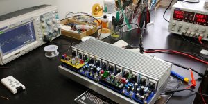
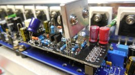
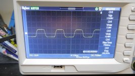
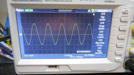
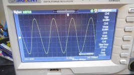
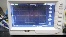
Here is what I came up with. It worked right away without any tweaking, and as far as I can tell from the oscilloscope, it looks very good
and stable. Doesn't show any crossover distortion as usual for quasi amps, even Baxandall diode wasn't needed (as opposed to similar amp built with FQA28N15 devices). Actually, real build behaves much better at 20kHz then simulations.
In simulation, drivers had to run at over 20mA to get rid of some crossover artifacts;
in real build 15mA was sufficient to get perfect results.
Slew rate is over 40V/us (way more then enough for a 25W amp).
This is schematic 'as built' with few exceptions: skipped R21, C17, 2N3904 instead MJE340.

but after some simulations I decided against it. I was left with number of logic-level N mosfets (HUF75842)
so since I needed to build a few of 20W quasi amps for someone else, I decided to use these devices and build Wiederhold77 style amp
(something like in post #326 and #313), but with these new devices. They are fast, cheap and have relatively low Cis.
Here is what I came up with. It worked right away without any tweaking, and as far as I can tell from the oscilloscope, it looks very good
and stable. Doesn't show any crossover distortion as usual for quasi amps, even Baxandall diode wasn't needed (as opposed to similar amp built with FQA28N15 devices). Actually, real build behaves much better at 20kHz then simulations.
In simulation, drivers had to run at over 20mA to get rid of some crossover artifacts;
in real build 15mA was sufficient to get perfect results.
Slew rate is over 40V/us (way more then enough for a 25W amp).
This is schematic 'as built' with few exceptions: skipped R21, C17, 2N3904 instead MJE340.
Attachments
-
 test_bench.jpg338 KB · Views: 177
 -
 square_20khz.jpg266.8 KB · Views: 134
 -
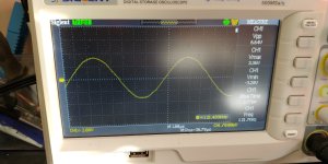 sine_120khz.jpg266.1 KB · Views: 148
 -
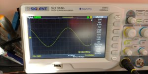 sine_20khz.jpg227.9 KB · Views: 131
 -
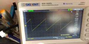 sawtooth_20khz.jpg281.5 KB · Views: 136
 -
wiederhold1977_qhex.huff.04.asc12.5 KB · Views: 100
-
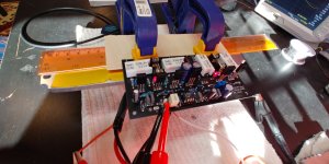 20231123_093517_HDR.jpg288.6 KB · Views: 192
 -
 thd_20khz.jpg66.3 KB · Views: 202
 -
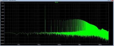 fft_20khz.jpg156.4 KB · Views: 220
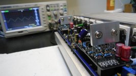
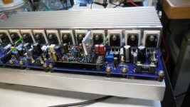
I was following Hayk's thread "1 EF Amp", and I realized that I have built an amp with a mirror-vas, almost like the one Hayk is proposing
(with Wilson mirror). That was last year, and seems like I forgot to publish it on this forum. Too many amps, I guess to keep track of.
So here it is:

The probe is located in wrong place, but that's how I simmed it 1 or 2 years ago, apparently it's stable enough as is....
With phase margin 74 there is enough room to cover for my probe placement 🙂
(with Wilson mirror). That was last year, and seems like I forgot to publish it on this forum. Too many amps, I guess to keep track of.
So here it is:
The probe is located in wrong place, but that's how I simmed it 1 or 2 years ago, apparently it's stable enough as is....
With phase margin 74 there is enough room to cover for my probe placement 🙂
Attachments
-
 DSCN0776.jpg100.9 KB · Views: 144
 -
 DSCN0772.jpg133.6 KB · Views: 121
 -
 DSCN0765.jpg133.8 KB · Views: 106
 -
 DSCN0764.jpg130.9 KB · Views: 117
 -
 DSCN0763.jpg132 KB · Views: 122
 -
 DSCN0761.jpg133.8 KB · Views: 112
 -
 DSCN0760.jpg132.8 KB · Views: 123
 -
 DSCN0757.jpg121.6 KB · Views: 141
 -
skraut.0.asc16 KB · Views: 95
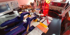
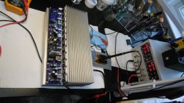
This is the box with almost all different Input/VAS modules I built so far my amp 'platform'... Most of the published in this thread.
The only inconvenience is that whenever I'm changing the module, I need to re-adjust the idle current in the OS.

The only inconvenience is that whenever I'm changing the module, I need to re-adjust the idle current in the OS.
They are all good. I rotate front-ends or whole amps every couple weeks.
Now I'm on wiederhold77 quasi hexfet...
Now I'm on wiederhold77 quasi hexfet...
I first saw this thread through the link in your post in the lineup thread. Excuse me It may have already been built, but I just noticed it.
#1,699 circuit diagram,
When the output saturates on the positive side during over-input, the base of Q1 is driven close to +15V (toward the reverse bias side), and I thought that it might exceed the emitter-base breakdown voltage (-5V) of the KSA992. Even if a breakdown current exceeds the withstand voltage and flows, if the current is limited, complete destruction may not occur. However, when a breakdown current flows between the emitter and base, it causes characteristic deterioration such as a decrease in hfe and an increase in base spread resistance. Since it is not destroyed, it is hard to notice and it can be said that it is even worse.
This may also occur in transient situations when the power is turned on and off.
- Home
- Amplifiers
- Solid State
- Unusual amp from 1987