Thanks Juma. Right, #1655 is not a quasi.
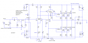
Here is the latest attempt for hexfet version. Current through Q4/Q8 is little bit over 8mA.
Over 100mA idle current per fet (I guess little high...).
All simmed result in line with previous latfet version from post #1655.
Base of Q10 grounded - this improves phase margin (compared with base connected to the OUT).
With hexfets of course some kind of temp sensor and idle current control will be needed here....
Any suggestions how to do that?
Attachments
Perhaps I should have said neither quasi nor monopolar amps (are worth the trouble), but I never called those amps quasi. Of course, monolithic (chip) amps are mostly going to be some kind of monopolar output, so there will be manufacturing etc pressures that will still resort to monopolar circuits. At least a quasi is somewhat cross coupled, driven from the same VAS vs other monopolar circuits where the conduction of the two outputs has no effect on each other and they are more sensitive to temperature and component variations. If any, they tend towards shoot through currents. Consider how the output reacts to external (back EMF) voltage/current applied to the output. If that reaction requires feedback all the way to the IPS and back, it's not going to be very quick or clean. A speaker voltage and current are almost never in phase like a resistor. We should probably do simulation with a speaker model instead of a resistor load. A CFP is short local feedback path around the lower OP. The only ~shorter path might be a resistor and I have done that, but a CFP also compares the VAS to the output with speed, albeit not as fast as an EF.
About slew rates and gate capacitance, VAS currents of 10 or 20 mA are probably enough for an audio amp but then VAS transistors get pretty hot, especially for amps bigger than 20 Watts. I notice a scan in another thread where a commercial amp used an NPN+PNP EF pair to drive a gate with no bias between them at all. I suppose that improves slew rate without adding distortion at lower frequencies as long as the quiescent point is not zero, or perhaps low frequency distortion is covered by plenty of feedback at those frequencies. Amps like the UCD have a local low voltage supply to drive gates that avoids the power wasted in a VAS doing the supply voltage times the peak gate current. Then you have potential bias pumping problems similar to what happens with a speed-up capacitor.
As it happens, I too, decided 10mA gate drive was enough, and the NPN driver came with complications so the latest version on my qmos circuit drops the NPN driver. (attached)
Attachments

Steve, something doesn't add up with your last sim. Upper fet idle current is over 400mA, while the lower one is 38uA...
I get 41mA and 38mA. The 3mA difference is the lower driver current. Are we using the same models? Mine are standard LTC. Both VBE multipliers would have to be tweaked with real parts. The VAS current is highly distorted but fixing that does not improve the amplifier so I'm studying alternatives.Steve, something doesn't add up with your last sim. Upper fet idle current is over 400mA, while the lower one is 38uA...
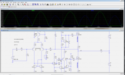
Here is my attempt to use your driver.
It works well - no crossover distortion at all.
However the whole amp didn't reach yet desired stability, or speed. SR: 20V/us only...
It needs huge (200p) caps at drivers' bases, I guess this might be slowing it down.
Traditional quasi Wiederhold77 that I built before, needed much smaller caps..
I'm still thinking that using non-quasi namp topology (like in post #1655), where lower fet is driven by inverted phase
should work better..
Attachments
You are right. I did change something (shorted C3). When it's not shorted, idle currents and offset are OK.
https://rcl-electro.ru/forums/Усилители-мощности-телефонные-усилители.33/Schemes open in a new tab without registering on the site.
Lots of good stuff in there. But it seems I still need an account/login to view images.
That's OK, I have an account.
That's OK, I have an account.
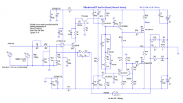
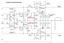
For your entertainment see attached. Any kind of ~quasi is not going to be as fast as an EF but maybe good enough? R27 is an old trick I used on LM377s many years ago when I wanted to use them for something besides audio amps, because the min gain was too high. The NPN+PNP gate buffer helps my QMOS circuit on the lower side but has little effect on the top side???? It should improve slew rate.
Attachments

Ya, only when the gate current exceeds Vbe/1k (fast slew). But I see the distortion @20KHz that I expected so forget that circuit. Well, let's say it needs work. With the lower Vto of the FETs that you use, etc, maybe a standard CFP quasi circuit is just as good. Many people just don't care if an amp clips miles (4V+) from the rail. My driver circuit provides a minimum gate voltage which means it does not have to slew far to get back to conduction (vto) at crossover. You could do that other ways as well, like a stack of diodes or LED. But a common source MOSFET needs a way to pull the gate ~8V above the drain during saturation. There was a post of a commercial amp that drove both FETS from ~10V above the output, but DIYA search rarely finds what I'm looking for. It had an (idle) current sensor in the power supply that adjusted the bias.
Another week - another amp 🙂
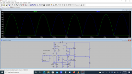
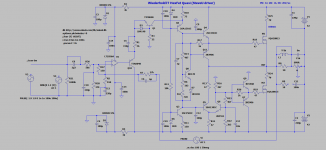
One more amp built - this one has nothing to do with Wiederhold/LMK topology featured in this thread,
except the fact that is uses folded cascode.
This is variation of Alexander amp. I posted this schematic back in August 2021, and finally managed to finish it.
It uses the chassis with Mosfet output stage that accepts daughter-boards, and this is the 3rd amp using it.
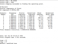
PhaseMargin: 81 degrees, GainMargin: 20dB, SlewRate 90 (sim).
Op-amp used: LT1056. TL071 wasn't performing well in tests.
Output DC offset +/- 2mV.
I guess transistors on the input board don't need heatsinks, they run at 35 - 55 degrees C.


One more amp built - this one has nothing to do with Wiederhold/LMK topology featured in this thread,
except the fact that is uses folded cascode.
This is variation of Alexander amp. I posted this schematic back in August 2021, and finally managed to finish it.
It uses the chassis with Mosfet output stage that accepts daughter-boards, and this is the 3rd amp using it.
PhaseMargin: 81 degrees, GainMargin: 20dB, SlewRate 90 (sim).
Op-amp used: LT1056. TL071 wasn't performing well in tests.
Output DC offset +/- 2mV.
I guess transistors on the input board don't need heatsinks, they run at 35 - 55 degrees C.
Attachments
-
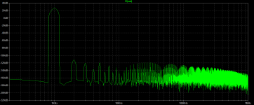 fft_1kHz.png13 KB · Views: 329
 -
 fft_20kHz.png13.1 KB · Views: 214
 -
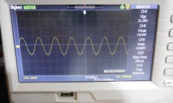 sin88.jpg341.6 KB · Views: 211
 -
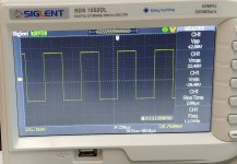 sq2.jpg168.5 KB · Views: 192
 -
 sq33.jpg205.8 KB · Views: 215
 -
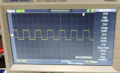 square1.jpg321.9 KB · Views: 245
 -
 thd_20kHz.png10 KB · Views: 263
 -
 thd_1kHz.png10.2 KB · Views: 258
 -
symmetrikal.alx_hawk.asc15.8 KB · Views: 129
-
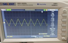 traingle.jpg250.3 KB · Views: 273

Good to see that "downscaled" version also works well. If you tie the 100nFs no further than 3mm from opamp legs and use separated ground tracks to local star ground you can use wide variety of opamps here.
These FQAs can easily oscillate, so I would select the value of gate resistors by measuring the input capacitance of the fets (sometimes there is a significant difference between the N and P devices) and choose the value of resistor based on the RC constant.
I just simulated this circuit with HEXFETs, it works well based on it, but its distortion is slightly higher than with FQAs.
Last edited:
I never tried it...Hi, Mr.Minek. What do you think about this..Will the bass be deeper, or leave your option?
- Home
- Amplifiers
- Solid State
- Unusual amp from 1987