I've been working on bigger, symmetrical Wiederhold amp, described in this thread:
Symmetrical amp clipping behavior - help needed
But I'm kind of hesitating - does it make sense to go symmetrical, or not?
Results (except slew rate) are similar (see above thread for screenshots).
Symmetrical is slightly better, but that's only the sim, where all transistors are identical.. I have doubts if real build will have any advantage.
Here is non-symmetrical version, that also looks promising.
Currently trying to increase phase margin...
Attachments
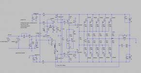

Symmetric with partial bootstrap
This is a symmetric variation that is fairly clean. I don't like (especially MOS) outputs that wastes several volts swing so this includes a partial bootstrap that reduces the output saturation to < 2V.
Note that the currents in the VAS are well defined. I would set the VAS current a bit higher than the stage before so that the VAS never reaches zero current, ie R19 > 2x R13.
I would probably add current limit if I actually built this.
BTW, IR640 are listed as obsolete.
Attachments
Last edited:
But I have more general hesitation regarding symmetrical vs. non-symmetrical approach. Symmetrical amps usually sim very well, but are these results really achievable in real world? Transistors that are supposedly complementary, are not exactly the same, and the whole concept of symmetry is suddenly gone.
Even pairs like 2SA1381 and 2SC3503 differ a lot. You can't even buy them in the same Beta groups... In the sim it all looks great..
Even pairs like 2SA1381 and 2SC3503 differ a lot. You can't even buy them in the same Beta groups... In the sim it all looks great..
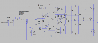
Symmetric IPS and P-P VAS
Typical symmetric IPS circuits, the VAS bias is inherited from the LTP rather than being defined locally, which means that part variations can mess up the bias badly.
Another issues with simulation is that supply voltage is "regulated" unless you go to the trouble to simulate supply ripple and variation in the simulation.
But P-P VAS can mean that the VAS can drive MOS outputs directly with reasonable slew rate, since you get twice the VAS current P-P for the same idle current and heat. LTC spice includes a "100W" amp example that has a P-P VAS but the bias is inherited from the LTP. The attached variation on the LTC "100W" example has a well defined VAS current and 140W @8 Ohms and much better THD from the same 50V supply.
Attachments

Input stage + VAS reminds of SYMASYM amp.
Very interesting bias control - kind of like what Elvee proposed for the 1st LMK amp in this thread?
Drivers are running at almost 300mW, need to be bigger.
You like to use C bootstraps everywhere 🙂
Will try to play with this sim.
Very interesting bias control - kind of like what Elvee proposed for the 1st LMK amp in this thread?
Drivers are running at almost 300mW, need to be bigger.
You like to use C bootstraps everywhere 🙂
Will try to play with this sim.
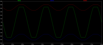
Imitate JVC amp to increase emitter follower
View attachment 935340
I tried that in couple of versions of these amps in this thread.
While it improves Thd and FFT profile very nicely, it also makes the amp very unstable (Phase Margin, Gain Margin extremly low).
Any bjt without a pull-off base resistor or current source is a thermal, RF rectification, and speed problem, including EF/ Darlington circuits. Transistor leakage and capacitance must be considered at every point.
The speed and therefore stability penalty of EF and cascode is less than a CE but it all adds up. For this reason, using an op-amp front end is difficult to stabilize.
DIYA has featured Darlington+cascode VAS circuits that oscillate all by themselves because the miller cap is a feedback path with no phase margin.
Avoiding global feedback is an oversimplified solution to the problem of putting too many stages inside the feedback loop.
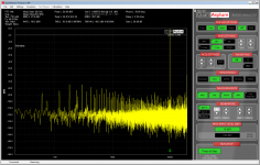
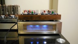
I finally managed to spend some time with QA401 audio analyzer.
First, had to build bigger 8 Ohm heatsinked 200W test load.
Still a lot to learn, but at least some results seem to make sense.
I decided to test LatFet Wiederhold amp from post #172
- at least don't need to worry about thermal runaway if it gets overheated..
This amp was designed and simulated for 100W RMS.
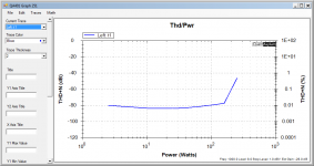
From these results looks like Thd (1kHz) is ranging from 0.0036% (2W)
to 0.0070% (25W). This is read from detailed test at each level.
Bulk test "Thd/Pwr" shows steady THD+Noise at below 0.01% until 150W (and then it starts to clip, and I can
hear the transformer buzzing slightly..)
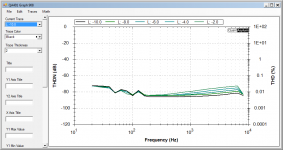
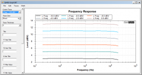
Noise levels (4th pic) are well below Yamaha and Technics amps I tried to compare it with.
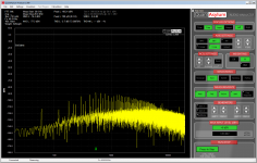
5th pic - 10kHz at 25W.
Frequency response looks very linear for all power levels (Highest plot for 0.0dBV corresponds to approx 50W).
It bends down a little close to 20 kHz.
First, had to build bigger 8 Ohm heatsinked 200W test load.
Still a lot to learn, but at least some results seem to make sense.
I decided to test LatFet Wiederhold amp from post #172
- at least don't need to worry about thermal runaway if it gets overheated..
This amp was designed and simulated for 100W RMS.
From these results looks like Thd (1kHz) is ranging from 0.0036% (2W)
to 0.0070% (25W). This is read from detailed test at each level.
Bulk test "Thd/Pwr" shows steady THD+Noise at below 0.01% until 150W (and then it starts to clip, and I can
hear the transformer buzzing slightly..)
Noise levels (4th pic) are well below Yamaha and Technics amps I tried to compare it with.
5th pic - 10kHz at 25W.
Frequency response looks very linear for all power levels (Highest plot for 0.0dBV corresponds to approx 50W).
It bends down a little close to 20 kHz.
Attachments
Last edited:
Most likely, the figures are overstated .The true Kg is lower .It is necessary to use an additional notch filter to increase the resolution of the analyzer .
There is another option to reduce all distortion while keeping the circuit simple, to use a composite opamp at the input. At the same time, the phase-frequency characteristics are significantly improved.If you are interested, I am ready to show you the diagram
What's Kg ?
>If you are interested, I am ready to show you the diagram
I'm always interested in this kind of stuff 🙂
>If you are interested, I am ready to show you the diagram
I'm always interested in this kind of stuff 🙂
Last edited:
Next weekend, I'll try to measure quasi BJT version of the same amp (with 2N3055 transistors).
I'm curious if there is going to be any measurable diferrence.
There better be 🙂
I'm curious if there is going to be any measurable diferrence.
There better be 🙂
I'm wondering about one thing: someone said previously in this thread, that amps with this kind vas (cascode) don't need to have slew rate as high as blameless amps. Is that actually true, and why ?
=====================
Меня интересует одна вещь: кто-то сказал ранее в этой теме, что усилители с таким типом VAS (каскодом) не должны иметь такую высокую скорость нарастания,
как безупречные усилители.
Это правда и почему?
=====================
Меня интересует одна вещь: кто-то сказал ранее в этой теме, что усилители с таким типом VAS (каскодом) не должны иметь такую высокую скорость нарастания,
как безупречные усилители.
Это правда и почему?
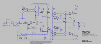
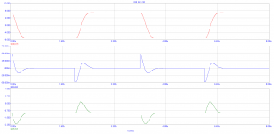
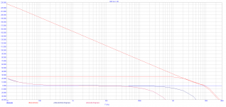
A phase-linear amplifier 020SLV with deep roots.Graphs of the analysis of the amplitude-frequency response and phase-frequency response, meander, IMD distortion of 19/20 kHz.
Attachments


Last edited:
Looks good!
This one is not driven from rails of the 2nd op-amp, like you had it before.
That's better, I had bad experience with driving vas from op-amp rails.
Will reproduce this in LTSpice.
=========================
Выглядит неплохо! Этот не приводится в движение от рельсов второго операционного усилителя, как это было у вас раньше. Так и лучше, у меня был плохой опыт вождения ВАС с рельсов ОУ. Воспроизведу это в LTSpice.
Can you post clean schematic without voltages, so I can see all component values ?
Edit: I see you just did!
Edit: I see you just did!
I'm wondering about one thing: someone said previously in this thread, that amps with this kind vas (cascode) don't need to have slew rate as high as blameless amps. Is that actually true, and why ?
=====================
Меня интересует одна вещь: кто-то сказал ранее в этой теме, что усилители с таким типом VAS (каскодом) не должны иметь такую высокую скорость нарастания,
как безупречные усилители.
Это правда и почему?
I won't argue about speed. Knowledge is not enough
Pay attention to the phase-frequency characteristics with a closed and open common oos .First pole 2-3 Hertz. 10Hz-20kHz phase does not changeCan you post clean schematic without voltages, so I can see all component values ?
Edit: I see you just did!
The first opump -OPA132/OPA134, the second opump-with a higher rate of rise of the output voltage.LM318 , LF357, AD744, and so on.
Last edited:
- Home
- Amplifiers
- Solid State
- Unusual amp from 1987