Maxim, in your vast library of these amplifiers you presented so far, do you have one with triple output, but with HexFets? For exmaple LMK with triple output with HexFets? Or can you propose modified output either for LMK or Wiederhold with a triplets/hexfet? I have too many HexFets, have to use them for something...
I only have bipolar transistors.Maxim, in your vast library of these amplifiers you presented so far, do you have one with triple output, but with HexFets? For exmaple LMK with triple output with HexFets? Or can you propose modified output either for LMK or Wiederhold with a triplets/hexfet? I have too many HexFets, have to use them for something...
Specify the type of transistors and the name
Last edited:
> ...triple output with HexFets - Has no practical sense?
"Output triples are seldom used in modern audio amplifiers.
The advent of modern high-gain, high quality semiconductor devices has minimized their usefulness, with few exceptions usually showing up
in custom esoteric designs." (Randy Slone).
So I guess there is NO practicality involved here, even with bipolars.
Now we are moving into 'esoteric' designs area 🙂 Even more so, with HexFets 🙂
I was just wondering IF there are any triple vertical fets outputs...
3EF
The only reason you need a driver for FETs is speed. At low frequencies a FET gate is VERY hi-impedance and can be driven with almost zero current. FET gates are capacitors about 1nF so if you have enough VAS current to achieve the slew rate that you want then you don't need a drive at all, much less two stages. Typically, you can get a clean 20KHz sine wave (no slew limiting) with no driver at all and you can get to 500Kz with just one driver stage, so there is no point in two driver stages.
By contrast, the base current of BJT outputs peaks around 500mA. A 2EF amp assumes good gain and no less than 8 Ohm load. So if you want to drive 2 or 4 Ohms, you need 3EF or a real high VAS current.
...triple output with HexFets - Has no practical sense?
The only reason you need a driver for FETs is speed. At low frequencies a FET gate is VERY hi-impedance and can be driven with almost zero current. FET gates are capacitors about 1nF so if you have enough VAS current to achieve the slew rate that you want then you don't need a drive at all, much less two stages. Typically, you can get a clean 20KHz sine wave (no slew limiting) with no driver at all and you can get to 500Kz with just one driver stage, so there is no point in two driver stages.
By contrast, the base current of BJT outputs peaks around 500mA. A 2EF amp assumes good gain and no less than 8 Ohm load. So if you want to drive 2 or 4 Ohms, you need 3EF or a real high VAS current.
Steve, so how about drivers for FET outputs?
Many of LatFet designs do without drivers, and output devices are driven directly from VAS.
Now, with vertical fets, they usually have drivers.
Any particular reason for this?
How LatFet differ from vertical fets in this situation?
"With regards to "no drivers" approach - HexFETs have got rather high and non-linear input capacitance (depends on Vgs), noticeably influencing VAS performance. Live measurements just confirm the theory - spectrums contain higher number of odd harmonics with higher levels. That's why I always add the follower - as soon as you drive the HexFETs with low impedance drivers, capacitance issue does not hurt any more.
Lateral FETs - completely different story. Those ones are designed for audio applications, capacitances are not that high and rather linear. Unfortunately I've got no graph for them, but again - live measurements show good results with them, being driven directly from the VAS, just a bit higher VAS quiescent current is recommended (8-10mA is good). All this beauty is also not given for free - lateral FETs are prone to local oscillation at very high frequencies (can exceed 100MHz), especially if more than one output pair is used. Well, not a show stopper - just needs to be addressed properly". According to Valery
Lateral FETs - completely different story. Those ones are designed for audio applications, capacitances are not that high and rather linear. Unfortunately I've got no graph for them, but again - live measurements show good results with them, being driven directly from the VAS, just a bit higher VAS quiescent current is recommended (8-10mA is good). All this beauty is also not given for free - lateral FETs are prone to local oscillation at very high frequencies (can exceed 100MHz), especially if more than one output pair is used. Well, not a show stopper - just needs to be addressed properly". According to Valery
I did build HexFet version of Lomakin-Parshin amp (1st one in this thread)
without drivers (post #110).
I could not see, hear or measure any difference.
without drivers (post #110).
I could not see, hear or measure any difference.
I did build HexFet version of Lomakin-Parshin amp (1st one in this thread)
without drivers (post #110).
I could not see, hear or measure any difference.
However - if I remember correctly - you didn't really like its sound.
Yeah, but that was very subjective feeling, I'm not sure about it.
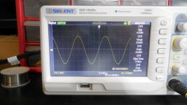
I guess will give it another try.. On the oscilloscope it looked perfect...
I guess will give it another try.. On the oscilloscope it looked perfect...
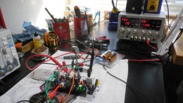
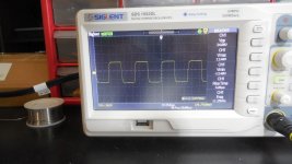
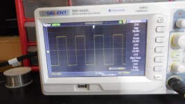
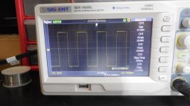
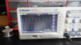
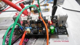
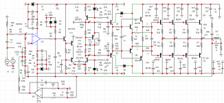
In the meantime - here is Quasi HexFet version running.
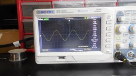
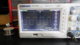
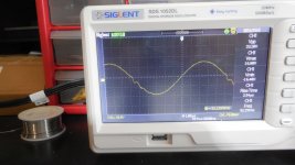
All looks good (no music tried yet) on the oscilloscope - with the exception
of small crossover distortion showing up on higher frequencies and higher amplitudes. See screenshots.
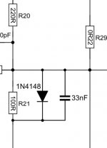
Tried to analyze it in the LTSpice; one way to minimize it would be to increase value of R1, but it's a trade of - it makes Thd on lower frequencies worse.
So, since it only shows up at very high frequencies,
perhaps it's something to live with... Should not affect regular music listening, I guess..
Well, it's a quasi...
Any suggestions?
BTW - the idle current pot really needs to be less sensitive 🙂
I just put 5k trimpot without extra resistors...
The heatsinks on small transistors are temporary, in the chassis , it's gonna be one big heatsink for all of them.
All looks good (no music tried yet) on the oscilloscope - with the exception
of small crossover distortion showing up on higher frequencies and higher amplitudes. See screenshots.
Tried to analyze it in the LTSpice; one way to minimize it would be to increase value of R1, but it's a trade of - it makes Thd on lower frequencies worse.
So, since it only shows up at very high frequencies,
perhaps it's something to live with... Should not affect regular music listening, I guess..
Well, it's a quasi...
Any suggestions?
BTW - the idle current pot really needs to be less sensitive 🙂
I just put 5k trimpot without extra resistors...
The heatsinks on small transistors are temporary, in the chassis , it's gonna be one big heatsink for all of them.
Attachments
-
 DSCN0354.JPG301.1 KB · Views: 727
 -
 DSCN0378.JPG246.2 KB · Views: 548
 -
 DSCN0377.JPG242.7 KB · Views: 530
 -
 DSCN0376.JPG250.4 KB · Views: 524
 -
 DSCN0375.JPG248.5 KB · Views: 538
 -
 DSCN0374.JPG242.4 KB · Views: 564
 -
 DSCN0372.JPG252.9 KB · Views: 714
 -
 DSCN0371.JPG254.3 KB · Views: 694
 -
 DSCN0365.JPG242.1 KB · Views: 722
 -
 DSCN0356.JPG296.8 KB · Views: 728
Last edited:
@minek. You can find a good explanation about FET driving issues. Unfotunately for some reason google doesn't allow to translate this page, but I put here this google translation. Sorry for the raw translation
"The MOS-FET (Metal-Oxide Semiconductor Field Effect Transistor) is a device that can be controlled with a very low input current. In theory, there would be no need for a separate drive stage between the voltage amplifier and the MOS-FET current amplifier stages, because the MOS-FET (in theory) is almost voltage controlled.
In practice, the situation is different. The MOS-FET has a high input capacity and behaves like a good long shielded cable in terms of control. Here, too, what we have previously discussed about cable drive for preamplifiers will apply. In some fast-signaling, high-voltage control situations, a sufficiently significant and quickly removable current is required to drive it. For this reason, a MOS-FET amplifier with good transient behavior can only be built with a high current drive stage with low output impedance. Now I’m saying that if you ever see a wiring diagram that doesn’t have a drive amplifier between the voltage amplifier stage and the MOS-FET, it’s ALL trash. In addition, a MOS-FET should only be driven with a transistor, otherwise we will only push the same problem one step away.
MOS-FETs can be of many types, many types have been developed over time, they do not behave in the same way, but I would not go into detail here due to space constraints. The type often used in audio power amplifiers is the lateral MOS-FET, a device with a negative temperature coefficient. This means that when the chip heats up, the opening voltage per unit current also increases, i.e. the device closes to heat. It is a very good feature because it does not require precisely adjusted control electronics, which would prevent heat run-off from occurring.
In the case of transistors, this works the other way around, the higher current opens the transistor better, which leads to even higher current, which opens even more, and so on. The MOS-FET re-regulates itself. This is also a kind of dynamic compression, although the extent of this is far from the same as that of an output transformer, and not so sudden. That is, the MOS-FET is able to transmit sudden signal changes with high currents, but it re-regulates it a little late and not too fast until its thermal state is balanced again according to its current. This process can be significantly reduced by intensive cooling of the MOS-FET. Unfortunately, a large heat sink is not enough for this, sophisticated solutions must be used to keep the dynamic heat change to a small value. Other types work differently, I wouldn’t go deeper into it here."
Audio erősitők – 5.resz - AudioWorld
And models with quasi have these communication distortions. Can it be necessary to increase the quiescent current ?In the meantime - here is Quasi HexFet version running.
All looks good (no music tried yet) on the oscilloscope - with the exception
of small crossover distortion showing up on higher frequencies and higher amplitudes. See screenshots.
Tried to analyze it in the LTSpice; one way to minimize it would be to increase value of R1, but it's a trade of - it makes Thd on lower frequencies worse.
So, since it only shows up at very high frequencies,
perhaps it's something to live with... Should not affect regular music listening, I guess..
Well, it's a quasi...
Any suggestions?
BTW - the idle current pot really needs to be less sensitive 🙂
I just put 5k trimpot without extra resistors...
The heatsinks on small transistors are temporary, in the chassis , it's gonna be one big heatsink for all of them.
I tried to increase idle current, makes no difference.
Each transistor is running at 35mA idle.
Tried up to 100mA, but it's the same behavior at higher frequencies.
Each transistor is running at 35mA idle.
Tried up to 100mA, but it's the same behavior at higher frequencies.
I will do this option
Parallel drivers? Is it better than one bigger driver?
- Home
- Amplifiers
- Solid State
- Unusual amp from 1987