Nad 314
Nad has allways been very conservative in their claims. In reality the amp delivers more than 80 watts for a short time, but not continues for one hour.
Also it is class G or "power envelope" as Nad calls it for high voltage spikes.
Thorsten
Nad has allways been very conservative in their claims. In reality the amp delivers more than 80 watts for a short time, but not continues for one hour.
Also it is class G or "power envelope" as Nad calls it for high voltage spikes.
Thorsten
Last edited:
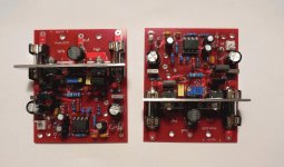
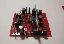
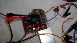
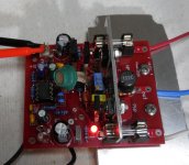
All right. Have the amp up and running.
See images.
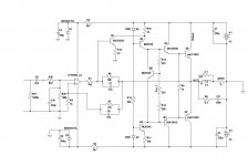
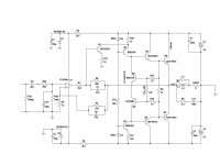
Some changes from initial version:
a) Q2/Q3 initially were 2SA1381/2SC3503. That didn't work out in
real build. Voltages at bases of drivers were all shifted couple of volts down.
Tried to replace them with MJE340/MJE350, and everything worked as in the sim.
My MJEs have similar (or perhaps slightly lower betas than 2SA/SC transistors).
So overall, I don't really know why MJEs work fine, and 2SA/SC don't.
In the sim they all worked fine..
b) In my 1st build, Q8 (Bias sensor) was 2N2222. Way to high beta, I guess. It affected output offset (1V..2V depending on BIAS).
Once replaced with MJE 340 (with beta 80), offset disappeared, and everything works just fine.
Could have used BD139, but real BD139 are getting harder to get by, and I have a whole bucket of MJEs, so I guess it will do.
When I was trying to solve issues with Q2/Q3/Q8, I also tried plain
biasing using single Si transistor (MJE340 in this case).
Also works just fine. I guess thermal compensation may differ from
original design with Si + Ge pair, but since I will cool this amp (as usual)
with heat pipes + fan + temperature controller, I guess it won't matter much, except for extreme cases.
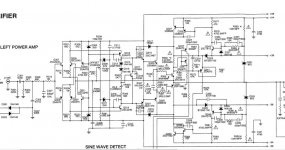
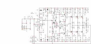
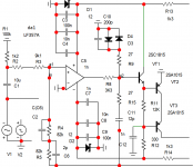
Have two versions now with different biasing, hence 2 different
schematics attached here - both of them - 'as built', except for the op-amp (TL071).
Not sure which biasing would be better to use. Since it took some effort and time to get Ge transistors, I should go with original scheme.
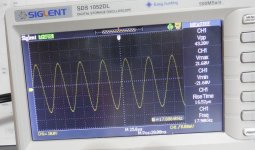
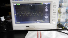
Tested with rails 42V, 8 Ohm resistive load.
Idle current little bit over 100mA, in final build will set it higher, to 160mA.
It clips little bit too soon, I think; not sure if it's fixable, or worth fixing - PSU have voltage overhead for my planned 80W output, so maybe it doesn't matter..
Slew rate about 10V/us, good enough for me, especially for such a simple amp, but will try later different op-amps.
Output voltage offset is minimal - less than 2mV in both versions, and does not seem to grow when running warmer.
See images.
Some changes from initial version:
a) Q2/Q3 initially were 2SA1381/2SC3503. That didn't work out in
real build. Voltages at bases of drivers were all shifted couple of volts down.
Tried to replace them with MJE340/MJE350, and everything worked as in the sim.
My MJEs have similar (or perhaps slightly lower betas than 2SA/SC transistors).
So overall, I don't really know why MJEs work fine, and 2SA/SC don't.
In the sim they all worked fine..
b) In my 1st build, Q8 (Bias sensor) was 2N2222. Way to high beta, I guess. It affected output offset (1V..2V depending on BIAS).
Once replaced with MJE 340 (with beta 80), offset disappeared, and everything works just fine.
Could have used BD139, but real BD139 are getting harder to get by, and I have a whole bucket of MJEs, so I guess it will do.
When I was trying to solve issues with Q2/Q3/Q8, I also tried plain
biasing using single Si transistor (MJE340 in this case).
Also works just fine. I guess thermal compensation may differ from
original design with Si + Ge pair, but since I will cool this amp (as usual)
with heat pipes + fan + temperature controller, I guess it won't matter much, except for extreme cases.
Have two versions now with different biasing, hence 2 different
schematics attached here - both of them - 'as built', except for the op-amp (TL071).
Not sure which biasing would be better to use. Since it took some effort and time to get Ge transistors, I should go with original scheme.
Tested with rails 42V, 8 Ohm resistive load.
Idle current little bit over 100mA, in final build will set it higher, to 160mA.
It clips little bit too soon, I think; not sure if it's fixable, or worth fixing - PSU have voltage overhead for my planned 80W output, so maybe it doesn't matter..
Slew rate about 10V/us, good enough for me, especially for such a simple amp, but will try later different op-amps.
Output voltage offset is minimal - less than 2mV in both versions, and does not seem to grow when running warmer.
Attachments
-
 DSCN0212.JPG153.5 KB · Views: 329
 -
 DSCN0215.JPG255.8 KB · Views: 198
 -
 DSCN0216.JPG258.4 KB · Views: 186
 -
 DSCN0219.JPG207.2 KB · Views: 215
 -
 DSCN0221.JPG174.7 KB · Views: 242
 -
 r1.jpg119 KB · Views: 259
 -
 DSCN0210.JPG141 KB · Views: 541
 -
 radio_1987_09_bjt_nrm.jpg94.1 KB · Views: 586
 -
 radio_1987_09_bjt.jpg99.9 KB · Views: 860
That's how this biasing with Si/Ge pair is called?
Not rejected, just trying different scheme to compare..
Not rejected, just trying different scheme to compare..
I also rejected the Alisson/Akulinichev shunt in favor of standard thermal stabilization in the next version .
I see you are using much lower values for caps in both feedback loops.
Perhaps I should try go lower than 47pF....
Also, I see you are using 'E' version of 2SA/SC transistors, so I guess more beta is better
in this cases?
Did you build it already?
Perhaps I should try go lower than 47pF....
Also, I see you are using 'E' version of 2SA/SC transistors, so I guess more beta is better
in this cases?
Did you build it already?
Last edited:
In the simulator, look at the denominations.I have a slightly different scheme.
I'll find a photo and show it to you. Now I'm making a new version
I'll find a photo and show it to you. Now I'm making a new version
Last edited:
Too early to thank .Thanks Stanislav!
Stanislav is my grandson. I'm Maxim.
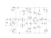
I decided to go with original (Akulinichev) biasing scheme with Ge transistors.
Both channels reconfigured to that scheme, all working fine.
With MJEs, it's a very stable amp, and overall cheap to build.
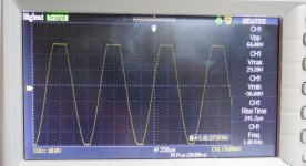
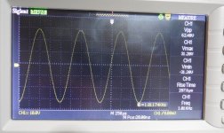
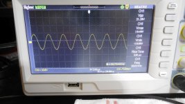
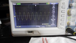
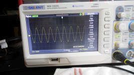
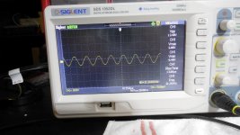
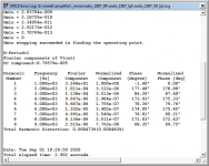
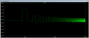
Few more wave tests for higher frequencies (42V rails, 100mA idle current per 1 output, resistive load 8 Ohm).
Final, 'as-built' schematic attached.
FFT and distortions simumlated at 90W, 1kHz.
Both channels reconfigured to that scheme, all working fine.
With MJEs, it's a very stable amp, and overall cheap to build.
Few more wave tests for higher frequencies (42V rails, 100mA idle current per 1 output, resistive load 8 Ohm).
Final, 'as-built' schematic attached.
FFT and distortions simumlated at 90W, 1kHz.
Attachments
Last edited:
D3/D4 ?
Equivalent of D5 between B-E of VAS transistor in your 1st schematic from yesterday?
Equivalent of D5 between B-E of VAS transistor in your 1st schematic from yesterday?
Last edited:
In your case a diode parallel to the emitter junction Q1 is sufficient .
Post 86 . D5
Post 86 . D5
Last edited:
- Home
- Amplifiers
- Solid State
- Unusual amp from 1987