Despite this output is biased 28ma, There is no any trace of crossover on the output at 10khz/30w, which measures 0.02%THD, 0.0009%1khz/1w.
Hayk
Attachments

Last edited:
This is the output impedance measured by +/-3A peak 10khz injected to the output with bias of only 86ma.
Attachments
Last edited:
Is it possible that this amplifier calls for hybrid nuvistor transistor parts that may benefit from some additional heat in the local oscilitory paths?
Perhaps the original part designs could be looked up and replaced with discrete nuvistors and modern silicon transistors.
Perhaps the original part designs could be looked up and replaced with discrete nuvistors and modern silicon transistors.
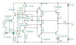
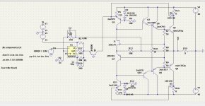
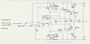
I returned back to the initial circuit of post 1 to remain faithful to the designers topology. I made it triple EF instead of two, but I canceled the VAS transistor. The opamp AD844 is a CFA intended for ultra performance I/V converter in DACs. I use it as transconductance error amplifier canceling it's pole, making the amp to behave as two stage, hence no compensation needed. I can not believe the distortion numbers measured both 10khz 1w&75w. Bias is 88ma
Of course this amp needs the habitual accessories to be added.
Hayk
Attachments
Last edited:
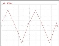
I tried to make in ltspice, but my version is oscillating like crazy..
Will check out yours...
What exactly is the purpose of R13 in the bias spreader?
Will check out yours...
What exactly is the purpose of R13 in the bias spreader?
Last edited:
It is local current feedback of the output stage transforming it low impedance . To note that this amplifier doesn't have a VAS stage followed by emitter followers, the 3 EFs function as current amplifiers current driven by error amplifier the AD844. As it functions upon ic/ib character instead of ic/vbe of transistors , it should give a different kind of sound than habitual SS sound.
Hayk
Hayk
Last edited:
1) This sim is very 'fragile' in the sense that changing one transistor to a different,
reasonable type (E.g Q2/Q11 to KSA992/KSC1845) makes it unstable.
The same goes with other transistors.
2) Another observation: symmetry and DC offset depends on current flowing through R5/R11 (tolerances!).
How DC offset can be set/stabilized in real amp? Would a trimmer be sufficient?
3) I still don't see any difference with or without R13. Same sim results..
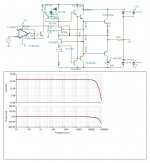
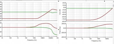
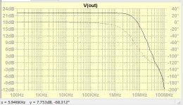
The bellow curves are the output impedance with R13 50k & 50M. You can see that the 50k keeps the output impedance to 1m ohm up to above 100khz what ever the input stage response. Here the circuit is not compensated with 20Mhz in closed loop.
The output stage in LT has different distortion than in Tina, I will investigate first the cause, after I deal with compensation. The offset can be resolved by adding a capacitor in series with R2 or a servo.
The output stage in LT has different distortion than in Tina, I will investigate first the cause, after I deal with compensation. The offset can be resolved by adding a capacitor in series with R2 or a servo.
Attachments
This is the compensated version of AD844 driven. It measures 0.00003%THD 10khz at 10w.
Attachments

Last edited:
Hi Hayk, will play with this when my Internet service is back.
I'm down for over 2 days now, due to that stupid 'tropical storm'...
I'm down for over 2 days now, due to that stupid 'tropical storm'...
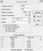
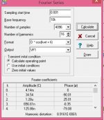
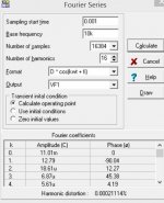
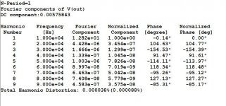
The distortion of the AD844 driven version at 1khz/1W is 0.00002%
Harmonic Frequency Fourier Normalized Phase Normalized
Number [Hz] Component Component [degree] Phase [deg]
1 1.000e+03 4.102e+00 1.000e+00 -0.01° 0.00°
2 2.000e+03 5.166e-07 1.260e-07 91.25° 91.26°
3 3.000e+03 6.107e-07 1.489e-07 -175.59° -175.57°
4 4.000e+03 3.315e-08 8.083e-09 94.05° 94.06°
5 5.000e+03 1.789e-07 4.361e-08 -174.22° -174.21°
6 6.000e+03 1.253e-08 3.055e-09 99.01° 99.03°
7 7.000e+03 4.824e-08 1.176e-08 -166.66° -166.64°
8 8.000e+03 5.291e-09 1.290e-09 98.83° 98.84°
9 9.000e+03 1.145e-08 2.790e-09 -168.22° -168.20°
Total Harmonic Distortion: 0.000020%(0.000000%)
This number can still be devided by 10 if compensated by 270pf with less slew rate and higher transient distortion. The THD at 10khz/64W is 0.00009%.
Hayk
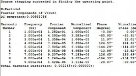
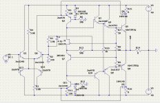
Nad similarity
Hi Hayk!
Your schematics in post 75 and 76 is allmost axactly like Nad 304/314:
Complementary diferential input, from the second leg to folded cascode, trippel emiterfollower and no emiterresistors at output.
But not the clever bias system.
Check it out at hifiengine.com.
By the way, Nad did not use emiterresistors in the 3020/302/312 either.
Thorsten Larsen ��
Last edited:
- Home
- Amplifiers
- Solid State
- Unusual amp from 1987