"It doesn't make much sense to use single transistor input (why? to save 50 cents over op-amp?),
and then put op-amp as a servo..."
This structure gives great room for creativity, including applying singleton input. Someone prefer the sound of single tranistor over LTP and opamp, this is why I mentioned that. Two drawbacks need to be solved: low PSRR and offset fluctuations.
and then put op-amp as a servo..."
This structure gives great room for creativity, including applying singleton input. Someone prefer the sound of single tranistor over LTP and opamp, this is why I mentioned that. Two drawbacks need to be solved: low PSRR and offset fluctuations.
Last edited:
If that's the profile you like - why not..Q2 only for 2SA1381C, leave Q3 as MJE340
The first two transistors will work well on BF422/BF423. They should not heat up, but if the supply voltage is higher than + / -45 volts, you can put a 100-300 om resistor in the Q2 collector.
Last edited:
If that's the profile you like - why not..
come on.. this looks OK... Honestly it is the best setup so far..
12 hours later, minek built it😀😀
Last edited:
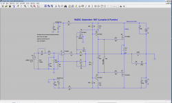
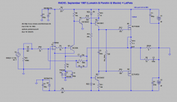
Here is sim file for Lomakin/Parshin + LatFets from post #358
Very simple amp - at the cost of LatFets from Exicon.
I happen to have a stash of ECW20N20/ECW20P20 - dual die Exicon Latfets, rated at 200W each (at 25 degrees).
So I guess just 1 pair of these devices should be good for an honest 100W amp, given that proper cooling is used.
Very simple amp - at the cost of LatFets from Exicon.
I happen to have a stash of ECW20N20/ECW20P20 - dual die Exicon Latfets, rated at 200W each (at 25 degrees).
So I guess just 1 pair of these devices should be good for an honest 100W amp, given that proper cooling is used.
Attachments
With the emitter repeater, the operational amplifier will not be skewed.The output of oramp will be 0 V DC.
>With the emitter repeater, the operational amplifier will not be skewed.The output of oramp will be 0 V DC.
This is regarding which schematic?
Which transistor is an "emitter repeater" in which schematic?
This is regarding which schematic?
Which transistor is an "emitter repeater" in which schematic?
But this is standard LMK, as built from Radio magazine.
The only change is BJTs => LatFets + few tweaks.
DC at the output of the whole amp is 0V in the one I built (post #97).
You didn't suggest anything like this back then...
The only change is BJTs => LatFets + few tweaks.
DC at the output of the whole amp is 0V in the one I built (post #97).
You didn't suggest anything like this back then...
Last edited:
What for?Then turn on the second transistor with a common base 🙂
Then turn on the second transistor with a common base 🙂
As wish.But this is standard LMK, as built from Radio magazine.
The only change is BJTs => LatFets.
DC at the output of the amp is 0V in the one I built.
Then turn on the second transistor with a common base 🙂
Then it will become Wiederhold amp 🙂
As wish.
Maxim, are you saying, LMK amp as described in Radio magazine (as in build from post #87), DOES need this emitter repeater?
If, as you say, output DC voltage on the op-amp is "skewed", what problems it is going to cause?
I don't see why this LMK amp (with latfets) would have better simulated results than Wiederhold amp?
Last edited:
What is 'correct' DC voltage at the output of the amp?
What is 'skewed' DC voltage at the output of the amp?
The one I built (LMK) has 1.1 V at the output of the opamp.
Wiederhold I built, has -1.56 V at the output of the opamp.
What is 'skewed' DC voltage at the output of the amp?
The one I built (LMK) has 1.1 V at the output of the opamp.
Wiederhold I built, has -1.56 V at the output of the opamp.
Last edited:
What is 'correct' DC voltage at the output of the amp?
What is 'skewed' DC voltage at the output of the amp?
The one I built (LMK) has 1.1 V at the output of the opamp.
Wiederhold I built, has -1.56 V at the output of the opamp.
In those ancient times, the output stages oramp were mostly low-power and with very low quiescent current, so due to the skew of the ramps, the operational amplifier switched to single-stroke amplification mode.And with a modern oramp, why do you need a constant voltage at the output ?
I personally, do not need DC voltage on the output 🙂
I guess Lomakin did, or he wanted to save 1 transistor.
Are you saying it should be 0V ?
But they seem to be working fine with non-zero DC output...
I guess Lomakin did, or he wanted to save 1 transistor.
Are you saying it should be 0V ?
But they seem to be working fine with non-zero DC output...
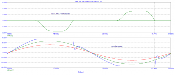
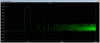
It will be even better. Anti-clip at least a decent make, and then in the clip at the output of the OU is a very large signal.
Here is a picture, an illustration.
This is the effect of nested OOS.
Anti-clip operation
Here is a picture, an illustration.
This is the effect of nested OOS.
Anti-clip operation
Attachments

Last edited:

- Home
- Amplifiers
- Solid State
- Unusual amp from 1987